Schede dello switch (32 porte NVMe)
La seguente tabella mostra i collegamenti dei cavi per la configurazione a 32 vani NVMe da 2,5" con quattro switch.
La sovrallocazione si verifica quando il sistema supporta 32 unità NVMe con adattatori switch NVMe. Per maggiori dettagli, vedere https://lenovopress.lenovo.com/lp1392-thinksystem-sr650-v2-server#nvme-drive-support.
| Da | A |
|---|---|
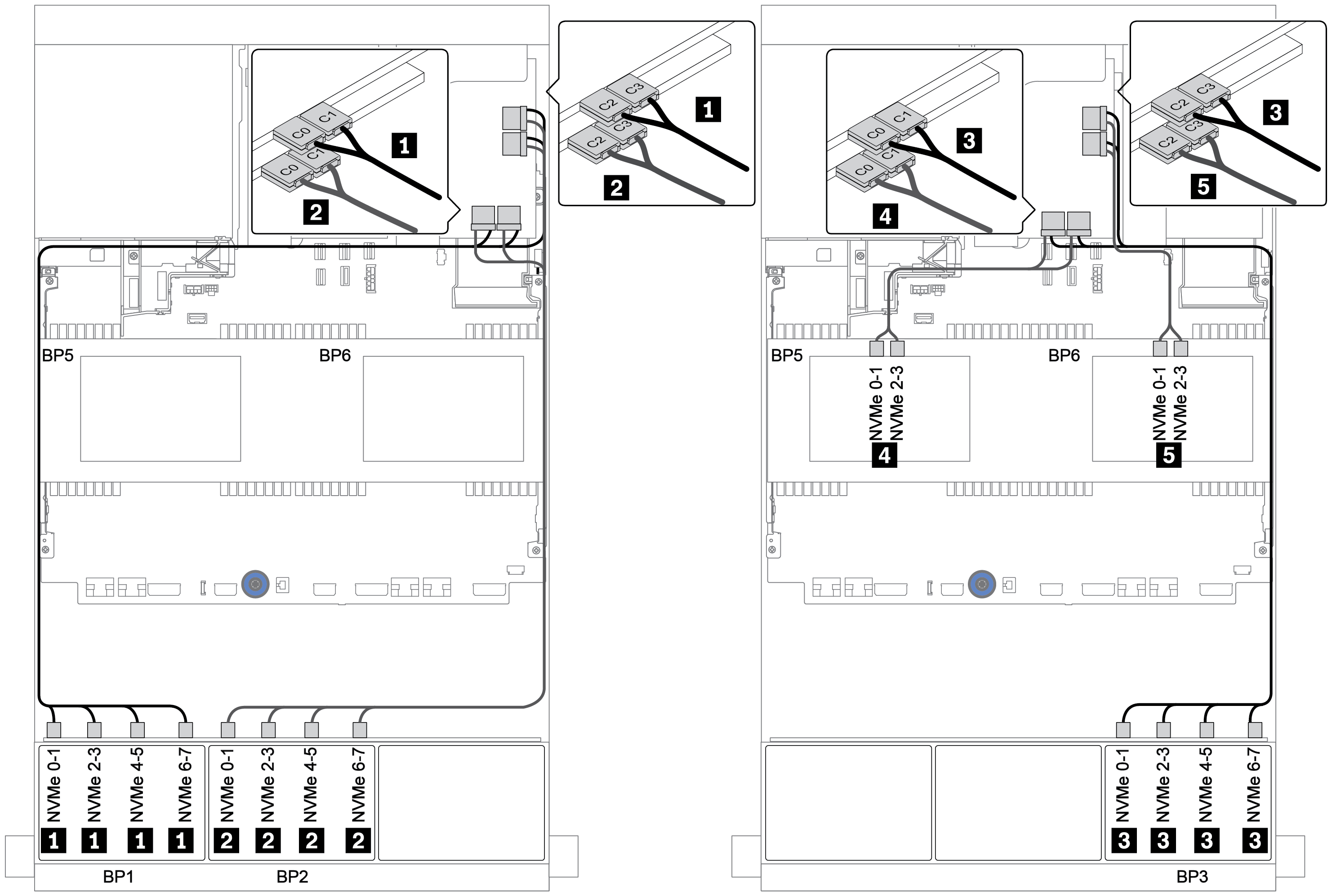
Backplane 1: NVMe 0-1, 2-3, 4-5, 6-7 | Scheda switch su slot PCIe 1: C0, C1, C2, C3 |
Backplane 2: NVMe 0-1, 2-3, 4-5, 6-7 | Scheda switch su slot PCIe 2: C0, C1, C2, C3 |
Backplane 3: NVMe 0-1, 2-3, 4-5, 6-7 | Scheda switch su slot PCIe 4: C0, C1, C2, C3 |
Backplane 5: NVMe 0-1, 2-3 | Scheda switch su slot PCIe 5: C0, C1 |
Backplane 6: NVMe 0-1, 2-3 | Scheda switch su slot PCIe 5: C2, C3 |
Collegamenti tra i connettori: 1 ↔ 1, 2 ↔ 2, 3 ↔ 3, ... n ↔ n