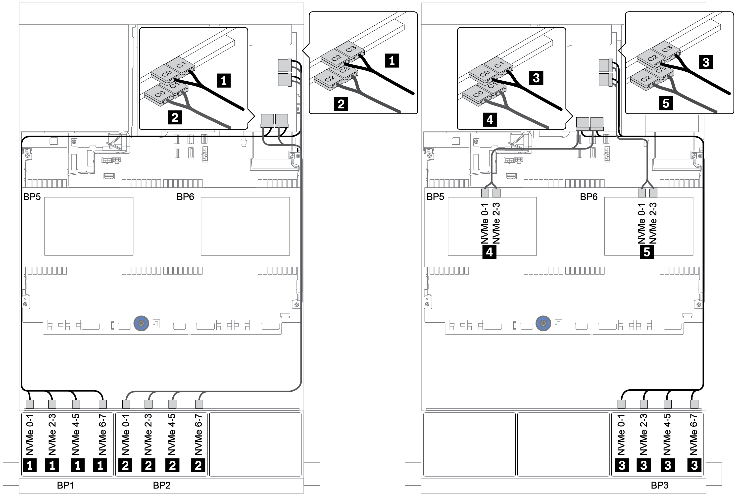
Switch cards (32 x NVMe)
The following shows the cable connections for the 32 x 2.5-inch NVMe configuration with four switch cards.
Note
Oversubscription occurs when the system supports 32 NVMe drives using NVMe switch adapters. For details, see https://lenovopress.lenovo.com/lp1392-thinksystem-sr650-v2-server#nvme-drive-support.
| From | To |
|---|---|
Backplane 1: NVMe 0-1, 2-3, 4-5, 6-7 | Switch card on PCIe slot 1: C0, C1, C2, C3 |
Backplane 2: NVMe 0-1, 2-3, 4-5, 6-7 | Switch card on PCIe slot 2: C0, C1, C2, C3 |
Backplane 3: NVMe 0-1, 2-3, 4-5, 6-7 | Switch card on PCIe slot 4: C0, C1, C2, C3 |
Backplane 5: NVMe 0-1, 2-3 | Switch card on PCIe slot 5: C0, C1 |
Backplane 6: NVMe 0-1, 2-3 | Switch card on PCIe slot 5: C2, C3 |
Connections between connectors: 1 ↔ 1, 2 ↔ 2, 3 ↔ 3, ... n ↔ n
Figure 1. Cable routing for the 32 x 2.5-inch NVMe configuration with four switch cards


Give documentation feedback