安装背面转接卡组合件
按以下信息安装背面转接卡组合件。

过程
- 将转接件组合件安装到机箱中。
转接件 1 组合件(转接件 2 组合件的操作与此相同)
注下图以 3 插槽转接卡架为例进行说明。单插槽转接卡架的更换过程与此类似。图 1. 安装转接件 1 组合件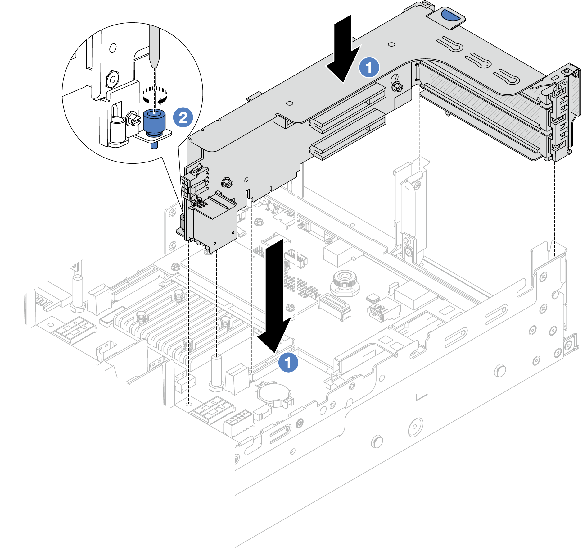
 将转接卡与主板组合件上的转接卡插槽对齐。小心地将转接卡笔直按入插槽,直至其牢固就位。
 拧紧螺钉以固定转接卡架。
转接件 3 组合件
注下图以 Gen 5 转接件 3 架为例进行说明。Gen 4 转接件 3 架的更换过程与之相同。图 2. 转接件 3 组合件安装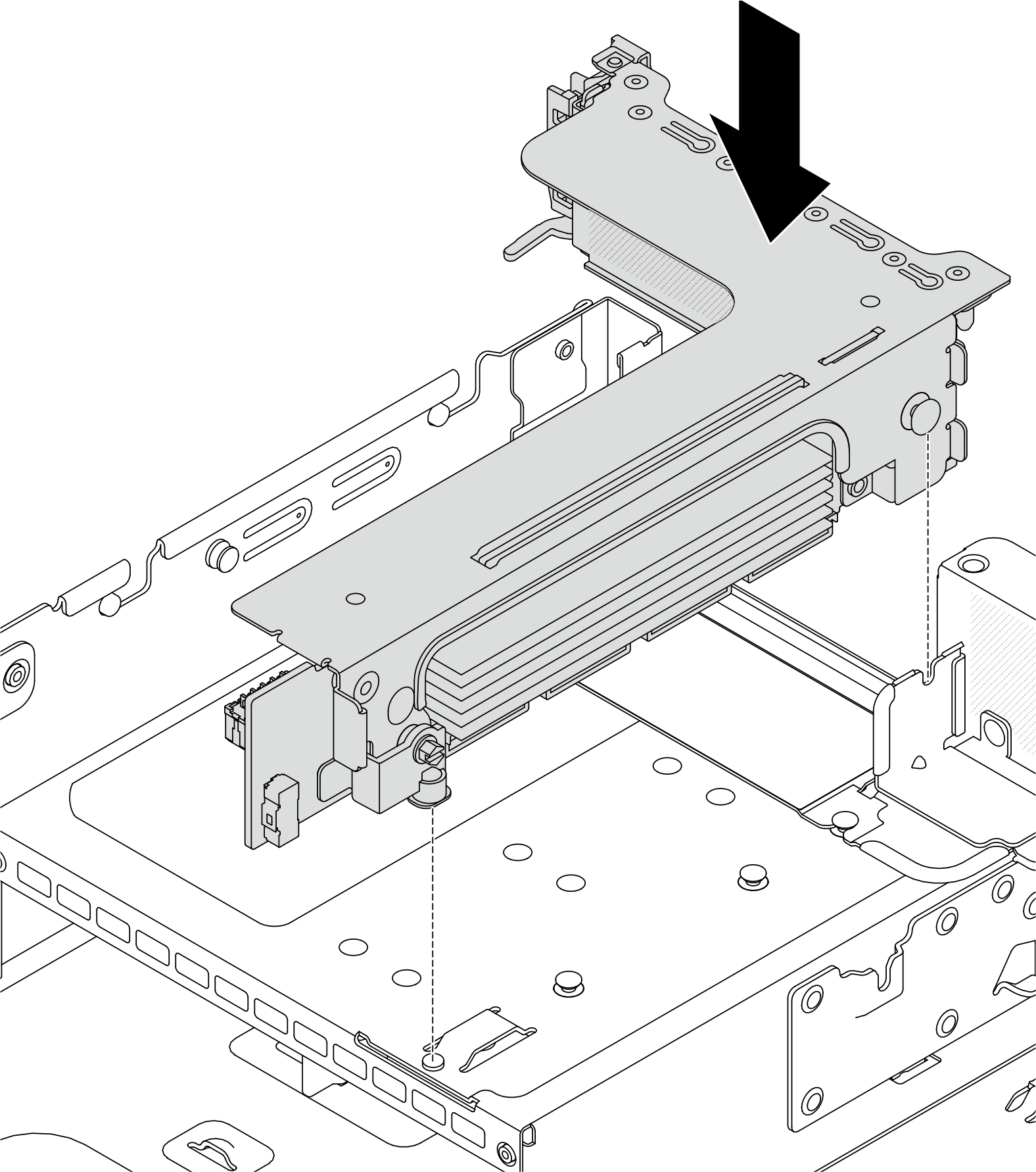
4LP 转接件 3/4 组合件
安装转接卡架托盘。
图 3. 安装转接卡架托盘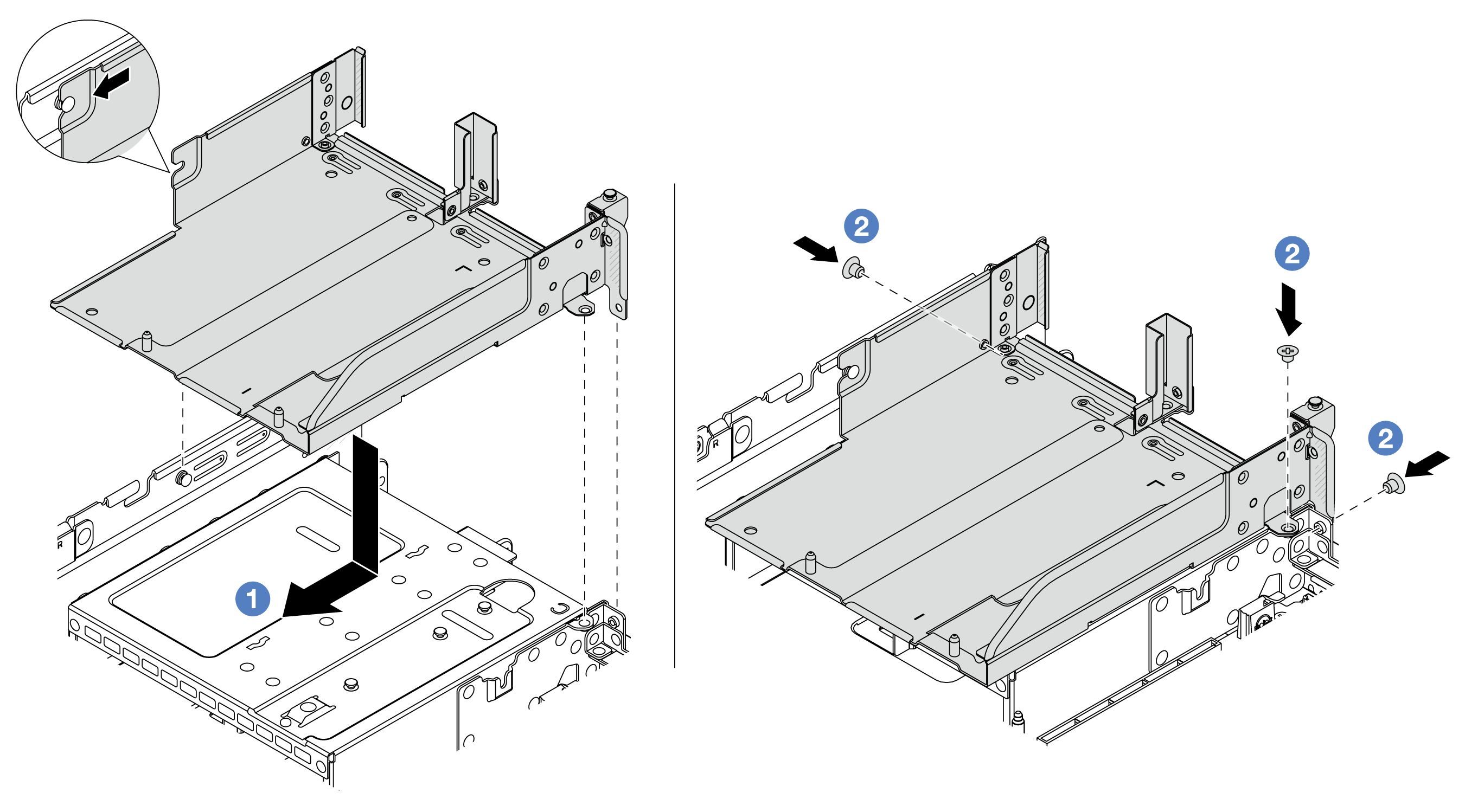
- 将转接卡架托盘与机箱上的定位销和螺钉孔对齐。
- 安装螺钉以将转接卡架托盘固定到机箱。
将转接件 3 组合件和转接件 4 组合件装入转接卡架中。
图 4. 安装转接件 3/4 组合件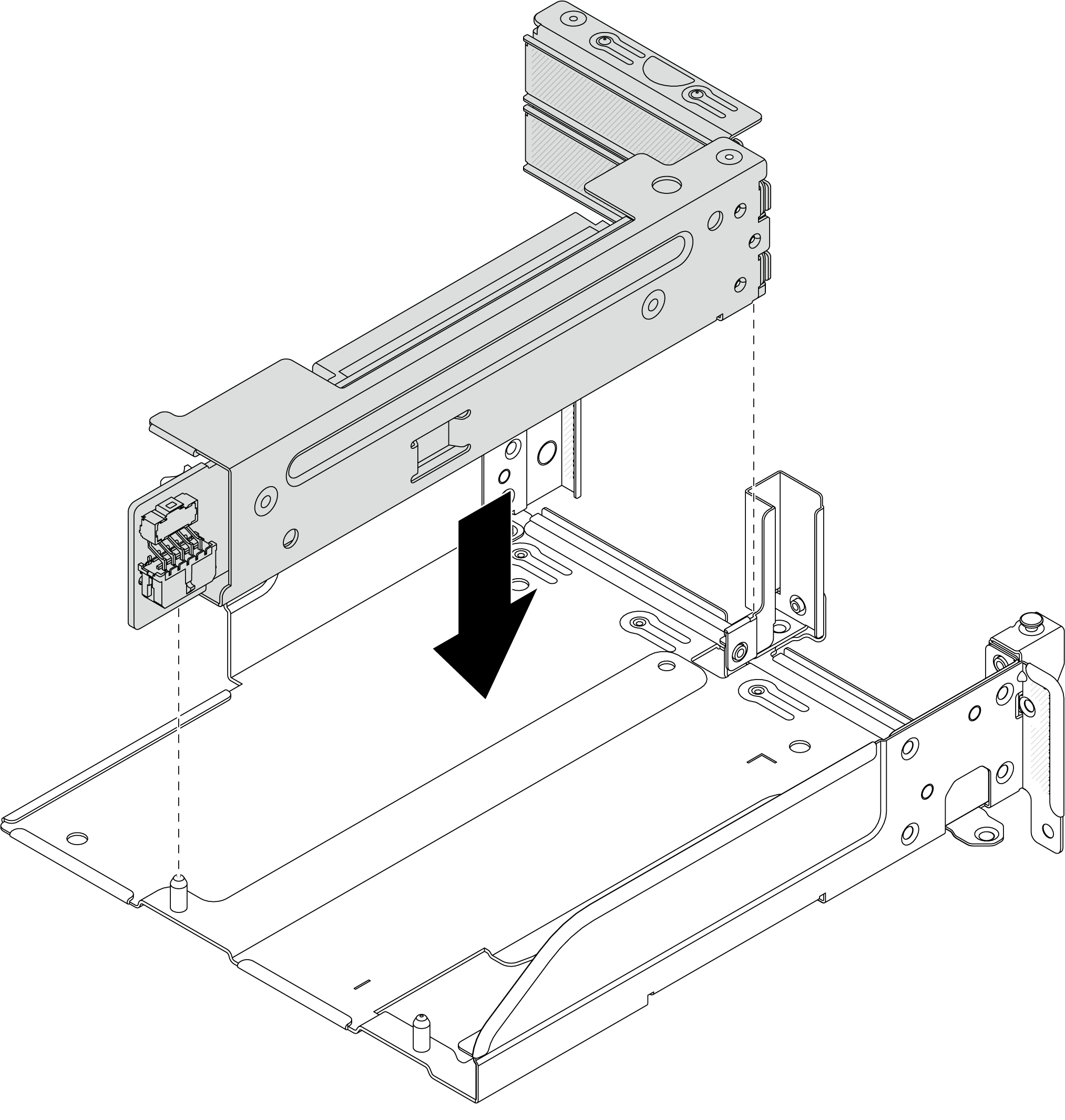
提供反馈