System board jumpers
The following illustration shows the location of the jumpers on the system board of your server.
Figure 1. System board jumpers
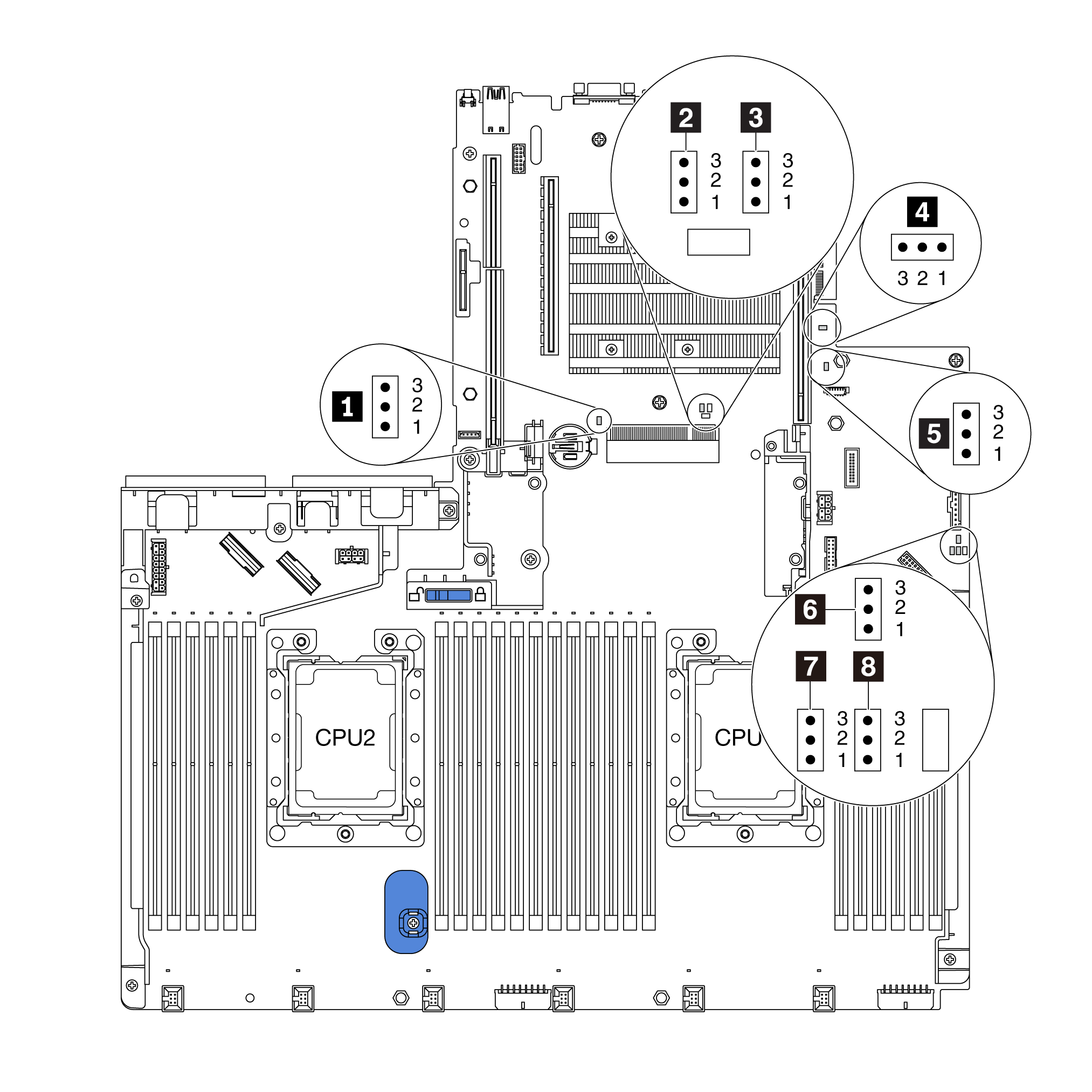
| Jumper / Switch name | Jumper / Switch number | Jumper / Switch setting |
|---|---|---|
| 1 Clear CMOS jumper | J95 |
|
| 2 Override power-on password jumper | J50 |
|
| 3 Boot backup XClarity Controller | J47 |
|
| 4 TPM/TCM physical presence jumper | J46 |
|
| 5 ME firmware security override | J30 |
Note For debug only. |
| 6 Force XCC update jumper | J45 |
|
| 7 Force XCC reset jumper | J181 |
|
| 8 Power permission | J49 |
|
Important
- Before you move any jumpers, turn off the server; then, disconnect all power cords and external cables. Do not open your server or attempt any repair before reading and understanding the following information:
- Any system-board switch or jumper block that is not shown in the illustrations in this document is reserved.
Give documentation feedback