System board LEDs
The illustration in this section shows the LEDs on the system board.
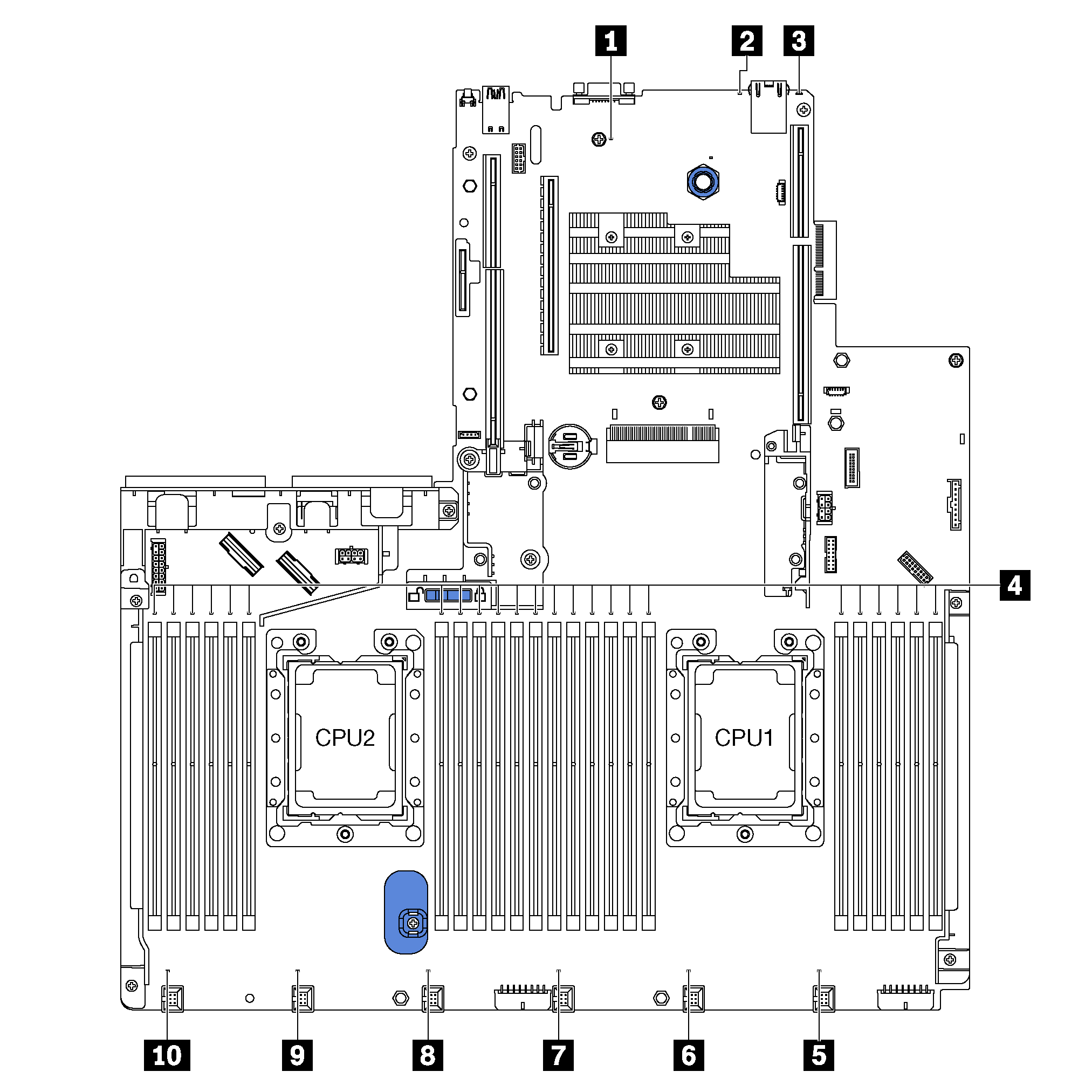
| Callout | Callout |
|---|---|
| 1 System power LED | 2 System ID LED |
| 3 System error LED | 4 memory module error LEDs (24) |
| 5 Fan 1 error LED | 6 Fan 2 error LED |
| 7 Fan 3 error LED | 8 Fan 4 error LED |
| 9 Fan 5 error LED | 10 Fan 6 error LED |
1 System power LED
When this LED is lit, it indicates that the server is powered on.
2 System ID LED
The blue system ID LED helps you to visually locate the server. A system ID LED is also located on the front of the server. Each time you press the system ID button, the state of both the system ID LEDs changes. The LEDs can be changed to on, blinking, or off. You can also use the Lenovo XClarity Controller or a remote management program to change the state of the system ID LEDs to assist in visually locating the server among other servers.
3 System error LED
When this yellow LED is lit, one or more LEDs elsewhere in the server might also be lit to direct you to the source of the error. For more information, see Front I/O assembly.
4 memory module error LEDs
When a memory module error LED is lit, it indicates that the corresponding memory module has failed.
5 6 7 8 9 10 Fan error LEDs
When a fan error LED is lit, it indicates that the corresponding system fan is operating slowly or has failed.