Front I/O assembly
The front I/O assembly of the server provides controls, connectors, and LEDs. The front I/O assembly varies by model.
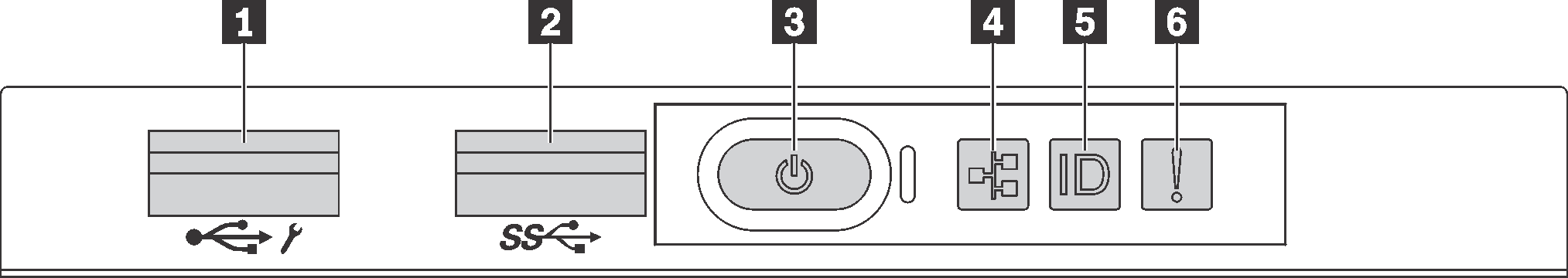
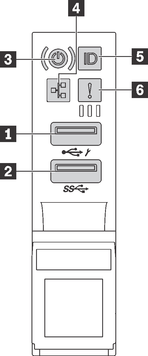
| Callout | Callout |
|---|---|
| 1 XClarity Controller USB connector | 2 USB 3.0 connector |
| 3 Power button with power status LED | 4 Network activity LED |
| 5 System ID button with system ID LED | 6 System error LED |
1 XClarity Controller USB connector
If the connector is set for USB 2.0 function, you can attach a device that requires a USB 2.0 connection, such as a keyboard, a mouse, or a USB storage device.
If the connector is set for XClarity Controller management function, you can attach a mobile device installed with the application to run XClarity Controller event logs.
If the connector is set to have both functions, you can press the system ID button for three seconds to switch between the two functions.
For more information, see Set the network connection for the Lenovo XClarity Controller.
2 USB 3.0 connector
Used to attach a device that requires a USB 2.0 or 3.0 connection, such as a keyboard, a mouse, or a USB storage device.
3 Power button with power status LED
| Status | Color | Description |
|---|---|---|
| Solid on | Green | The server is on and running. |
| Slow blinking (about one flash per second) | Green | The server is off and is ready to be powered on (standby state). |
| Fast blinking (about four flashes per second) | Green | The server is off, but the XClarity Controller is initializing, and the server is not ready to be powered on. |
| Off | None | There is no ac power applied to the server. |
4 Network activity LED
Compatibility of the NIC adapter and the network activity LED
| NIC adapater | Network activity LED |
|---|---|
| LOM adapter | Support |
| ML2 NIC adapter | Support |
| PCIe NIC adapter | Not support |
The network activity LED on the front I/O assembly helps you identify the network connectivity and activity.
| Status | Color | Description |
|---|---|---|
| On | Green | The server is connected to a network. |
| Blinking | Green | The network is connected and active. |
| Off | None | The server is disconnected from the network. |
5 System ID button with system ID LED
Use this system ID button and the blue system ID LED to visually locate the server. A system ID LED is also located on the rear of the server. Each time you press the system ID button, the state of both the system ID LEDs changes. The LEDs can be changed to on, blinking, or off. You can also use the Lenovo XClarity Controller or a remote management program to change the state of the system ID LEDs to assist in visually locating the server among other servers.
If the XClarity Controller USB connector is set to have both the USB 2.0 function and XClarity Controller management function, you can press the system ID button for three seconds to switch between the two functions.
6 System error LED
The system error LED provides basic diagnostic functions for your server. If the system error LED is lit, one or more LEDs elsewhere in the server might also be lit to direct you to the source of the error.
| Status | Color | Description | Action |
|---|---|---|---|
| On | Yellow | An error has been detected on the server. Causes might include but not limited to the following errors:
| Check the event log to determine the exact cause of the error. Alternatively, follow the light path diagnostics to determine if additional LEDs are lit that will direct you to identify the cause of the error. |
| Off | None | The server is off or the server is on and is working correctly. | None. |