Backplanes: server models with 2.5-inch front drive bays
This section provides backplane cable connection information for server models with 2.5-inch front drive bays.
Top cover (see Remove the top cover)
Air baffle (see Remove the air baffle)
Fan cage (see Remove the system fan cage)
For the server with a performance heat sink (T-shape), remove the heat sink first before disconnecting or connecting the cables which connect to PCIe 1, PCIe 2, PCIe 3, PCIe 4, PCIe 7, or PCIe 8 connectors (see the table below). After disconnecting or connecting the cables, install the heat sink back to the server. See Remove a heat sink and Install a heat sink
 |
|
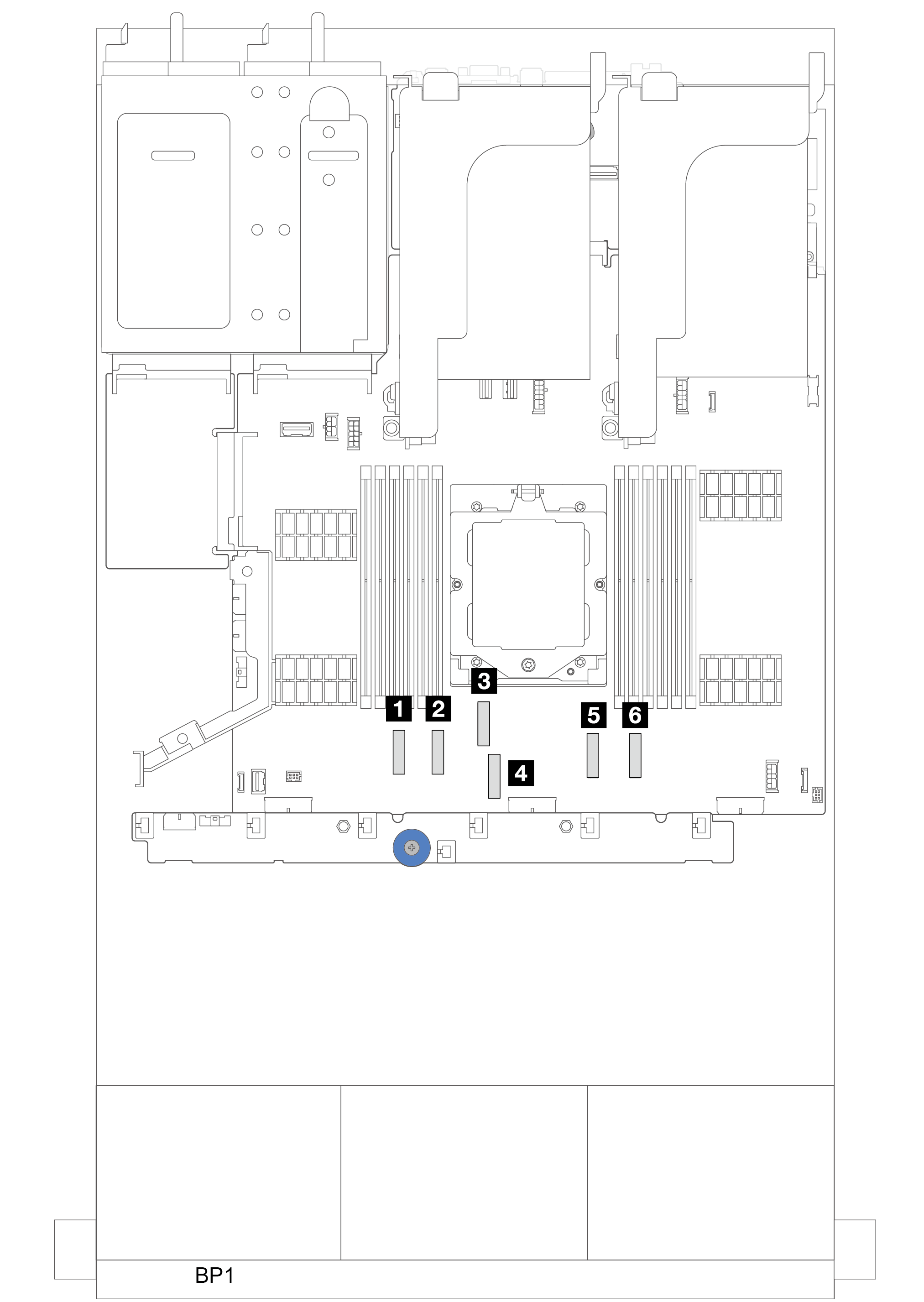
Power cable connections
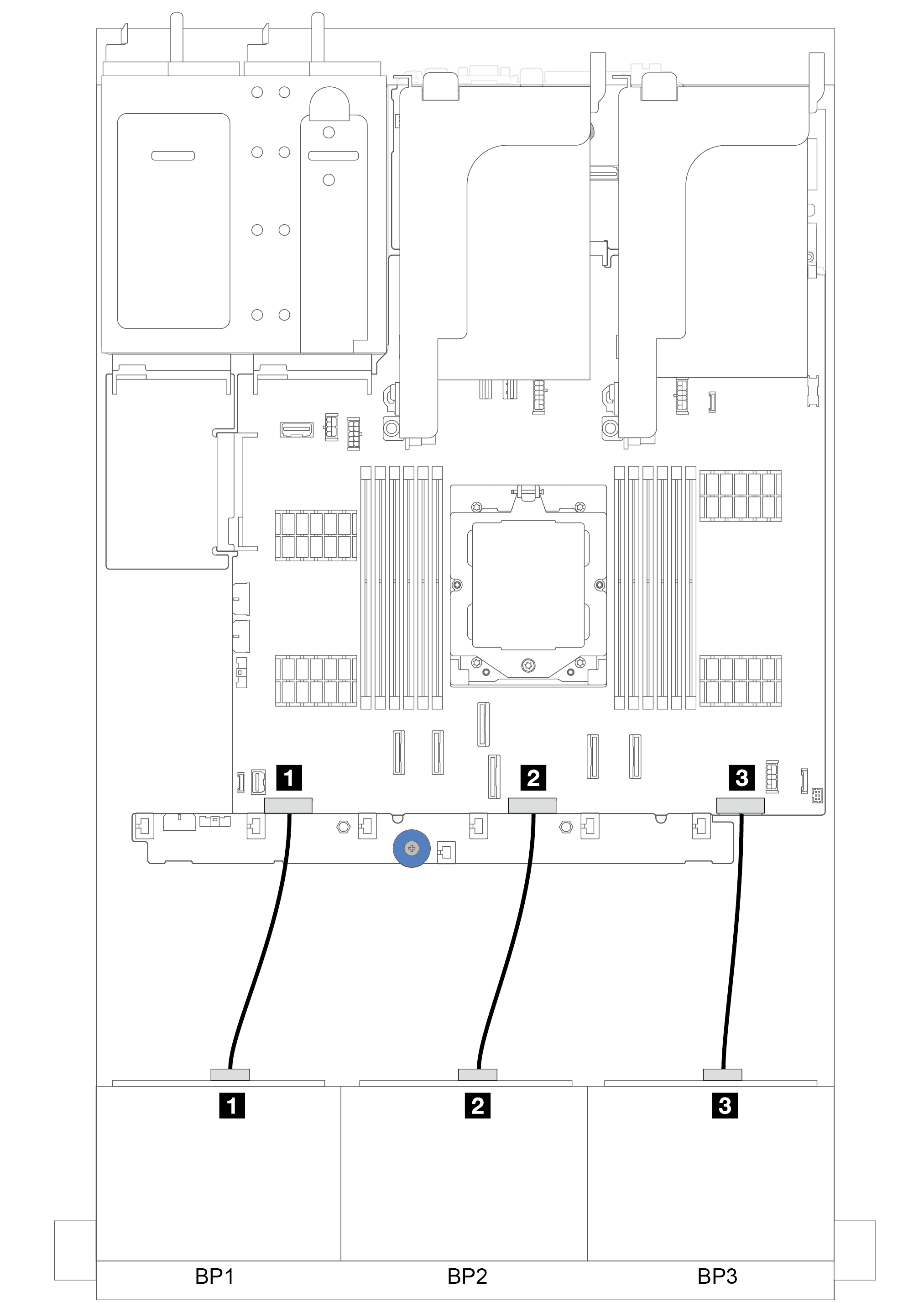
| Front drive backplane | Middle drive backplane | Rear drive backplane |
|---|---|---|
|
|
|
| From | To |
|---|---|
| 1 Backplane 1: PWR | 1 Backplane 1 power connector on the system board assembly |
| 2 Backplane 2: PWR | 2 Backplane 2 power connector on the system board assembly |
| 3 Backplane 3: PWR | 3 Backplane 3 power connector on the system board assembly |
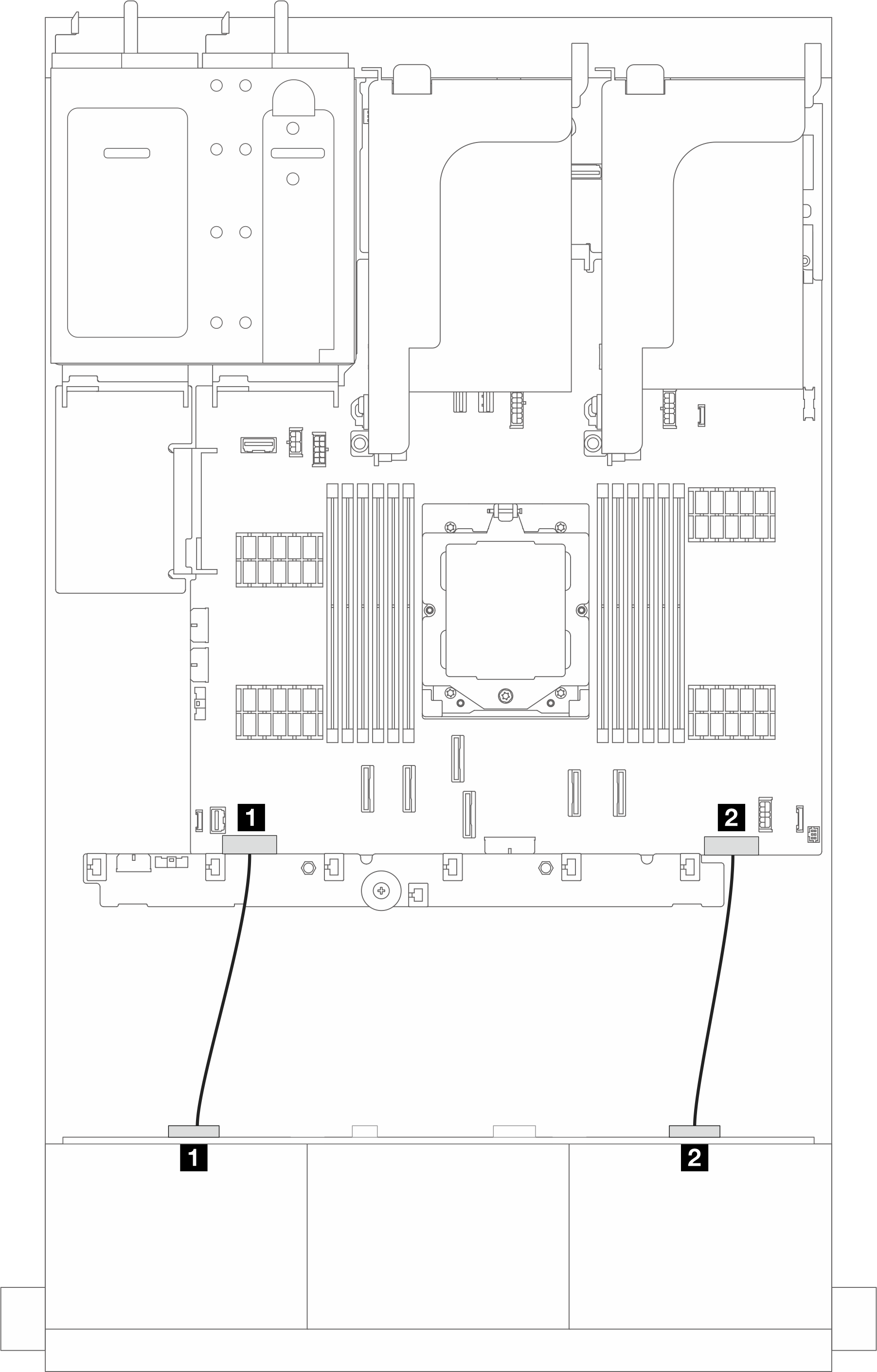
| From | To |
|---|---|
| 1 Backplane: PWR 1 | 1 Backplane 1 power connector on the system board assembly |
| 2 Backplane: PWR 2 | 2 Backplane 3 power connector on the system board assembly |
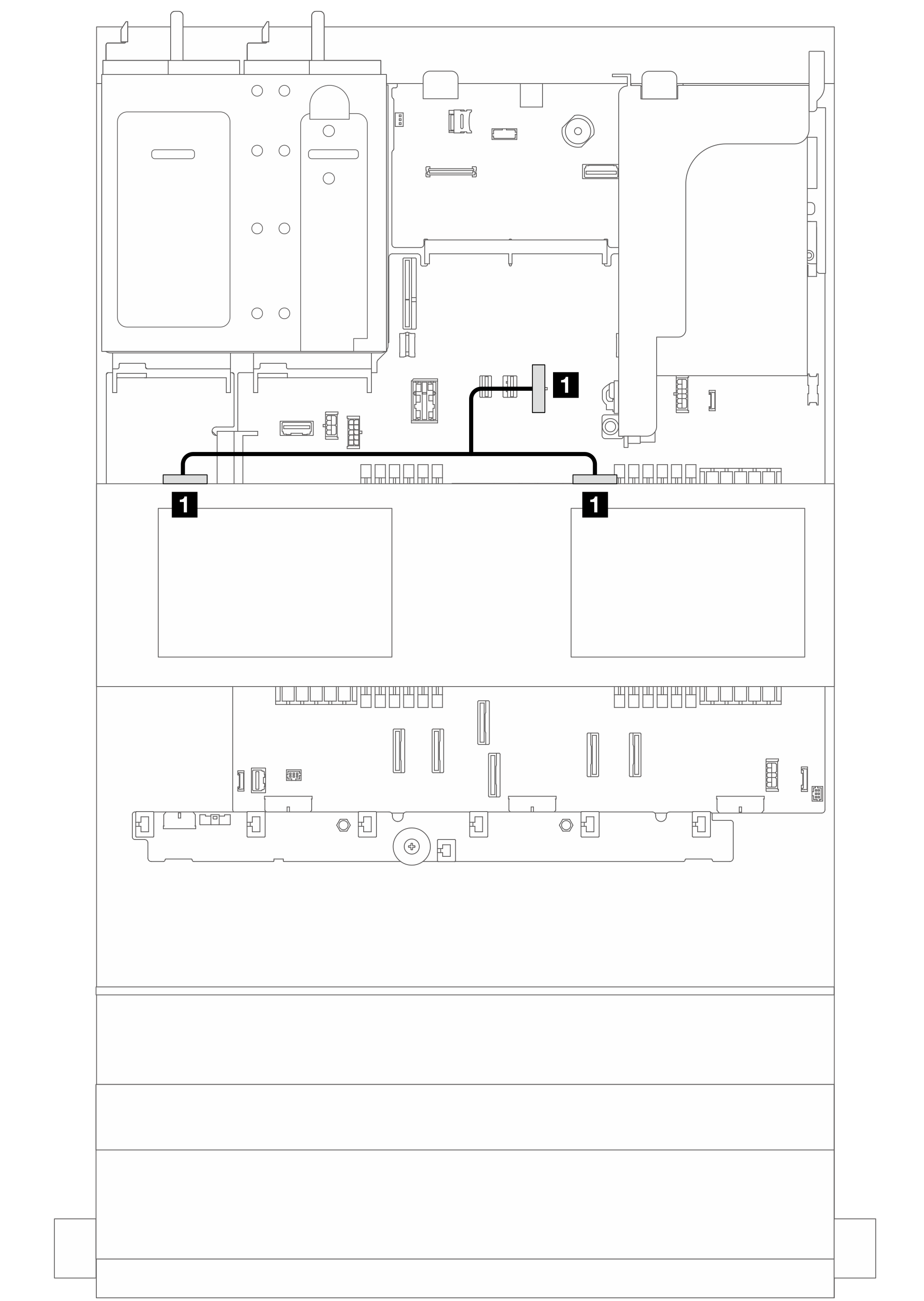
| From | To |
|---|---|
| 1 Power connector on the backplane | 1 Middle backplane power connector on the system board assembly |
Note The illustration above shows the power cable connection for using two middle drive backplanes. Power cable connection for using one middle drive backplane is similar. | |
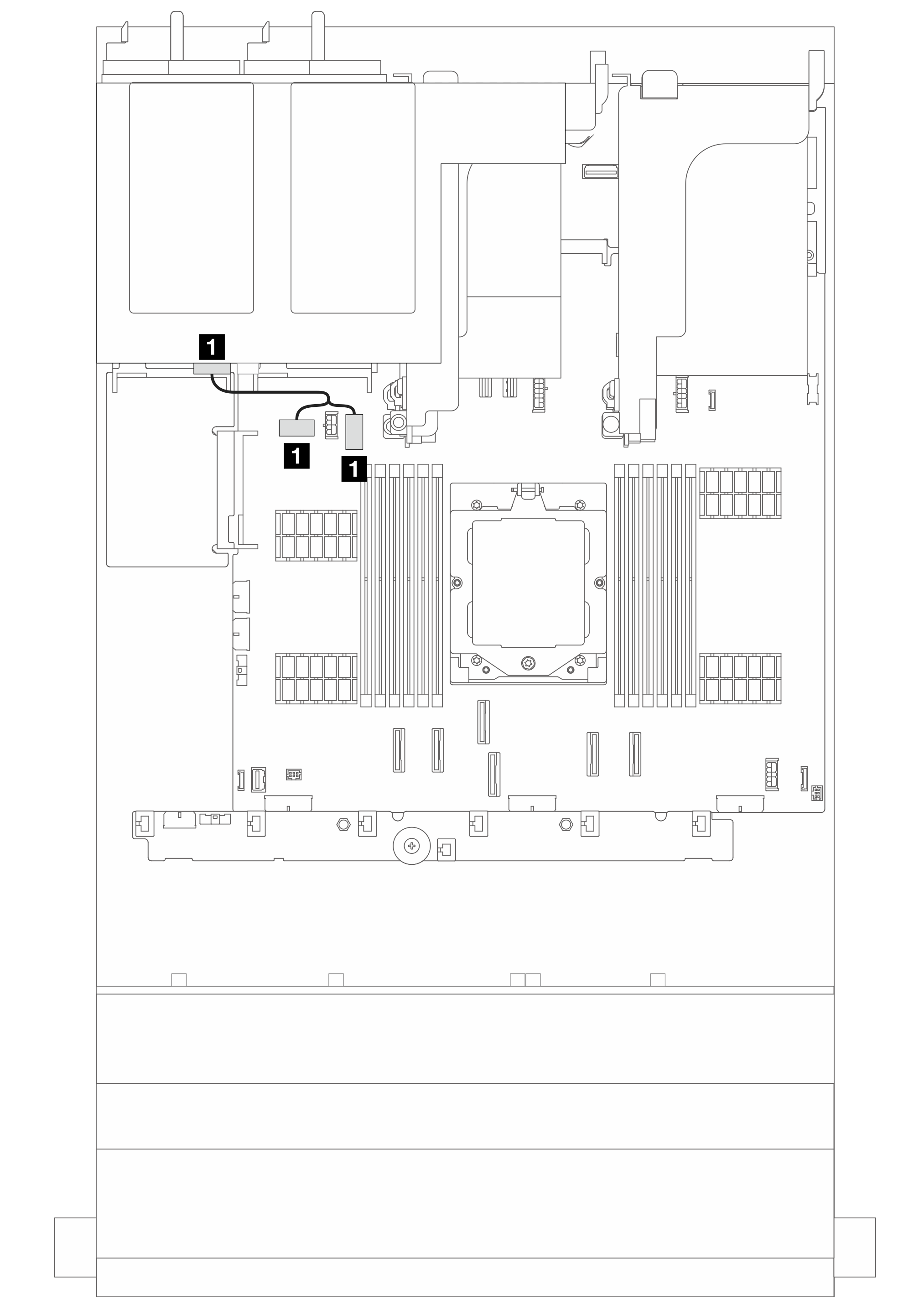
| From | To |
|---|---|
| 1 Power connector on the backplane | 1 Rear backplane power connector and sideband connector on the system board assembly |
Note The illustration above shows the power cable connection for one 4 x 2.5-inch rear drive backplanes. Power cable connection for using one 8 x 2.5-inch rear drive backplane is similar. | |
Signal cable connections
Refer to the specific topic for signal cable connections depending on the backplanes installed.