Backplanes: server models with 3.5-inch front drive bays
This section provides backplane cable connection information for server models with 3.5-inch front drive bays.
Before you start
Top cover (see Remove the top cover)
Air baffle (see Remove the air baffle)
Fan cage (see Remove the system fan cage)
For the server with a performance heat sink (T-shape), remove the heat sink first before disconnecting or connecting the cables which connect to PCIe 1, PCIe 2, PCIe 3, PCIe 4, PCIe 7, or PCIe 8 connectors (see the table below). After disconnecting or connecting the cables, install the heat sink back to the server. See Remove a heat sink and Install a heat sink
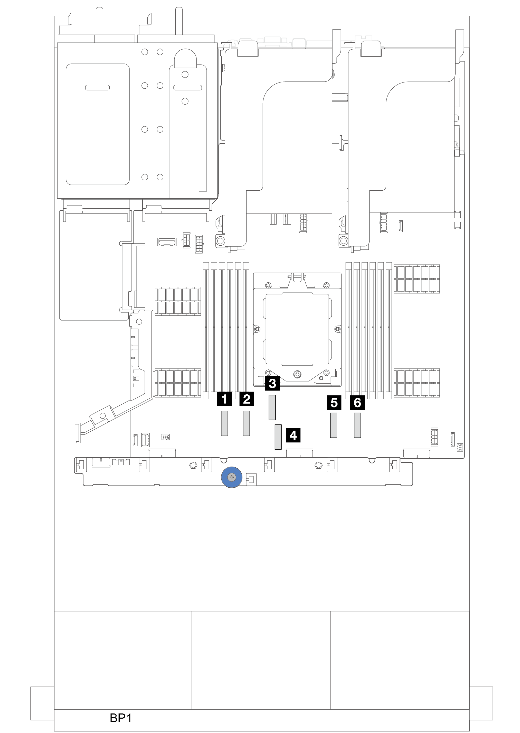 |
|
Power cable connections
For the 3.5-inch drive bay chassis, the following backplanes are supported and connect the power cables for the supported drive backplanes as illustrated.
| Front drive backplane | Middle drive backplane | Rear drive backplane |
|---|---|---|
|
|
|
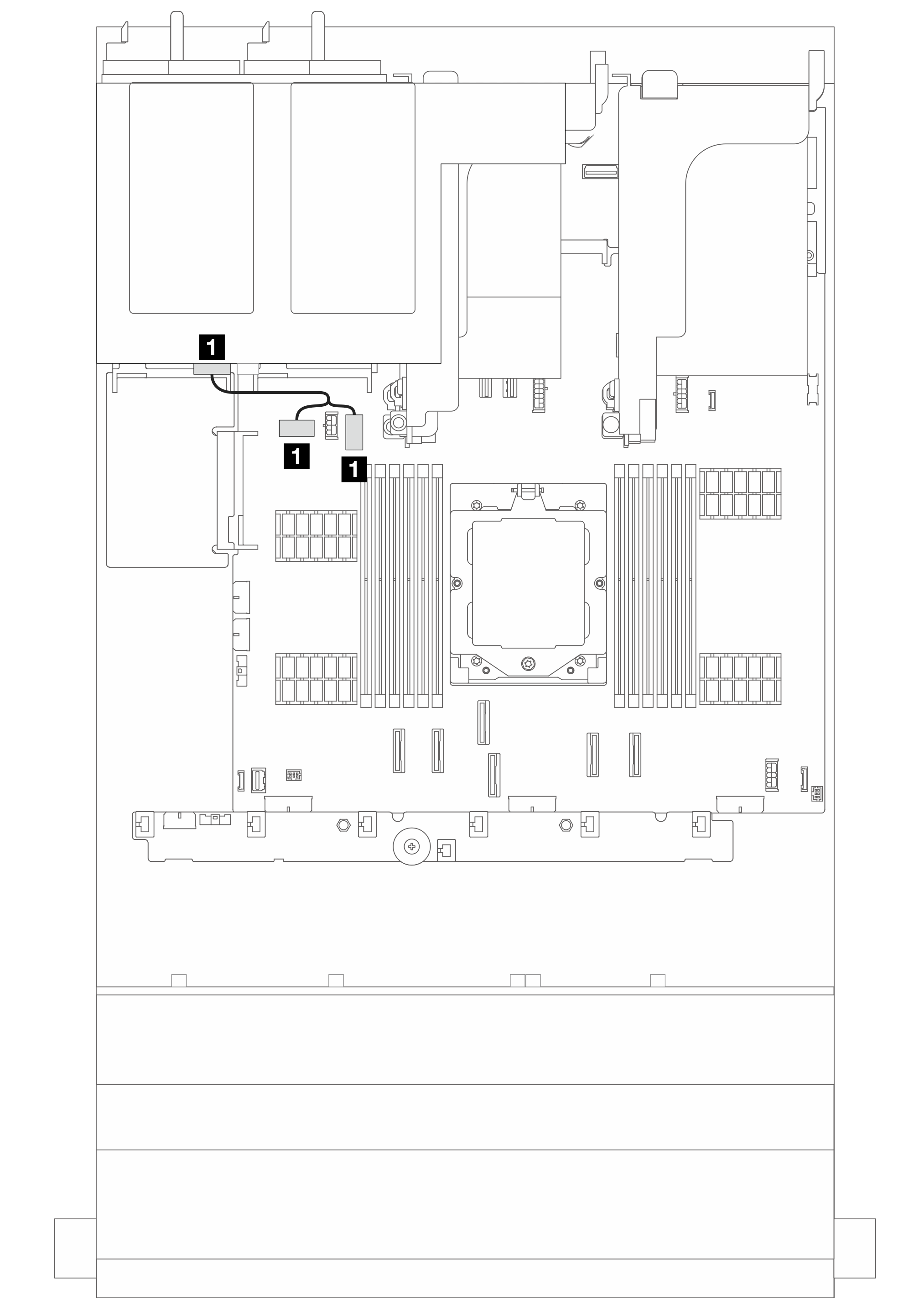
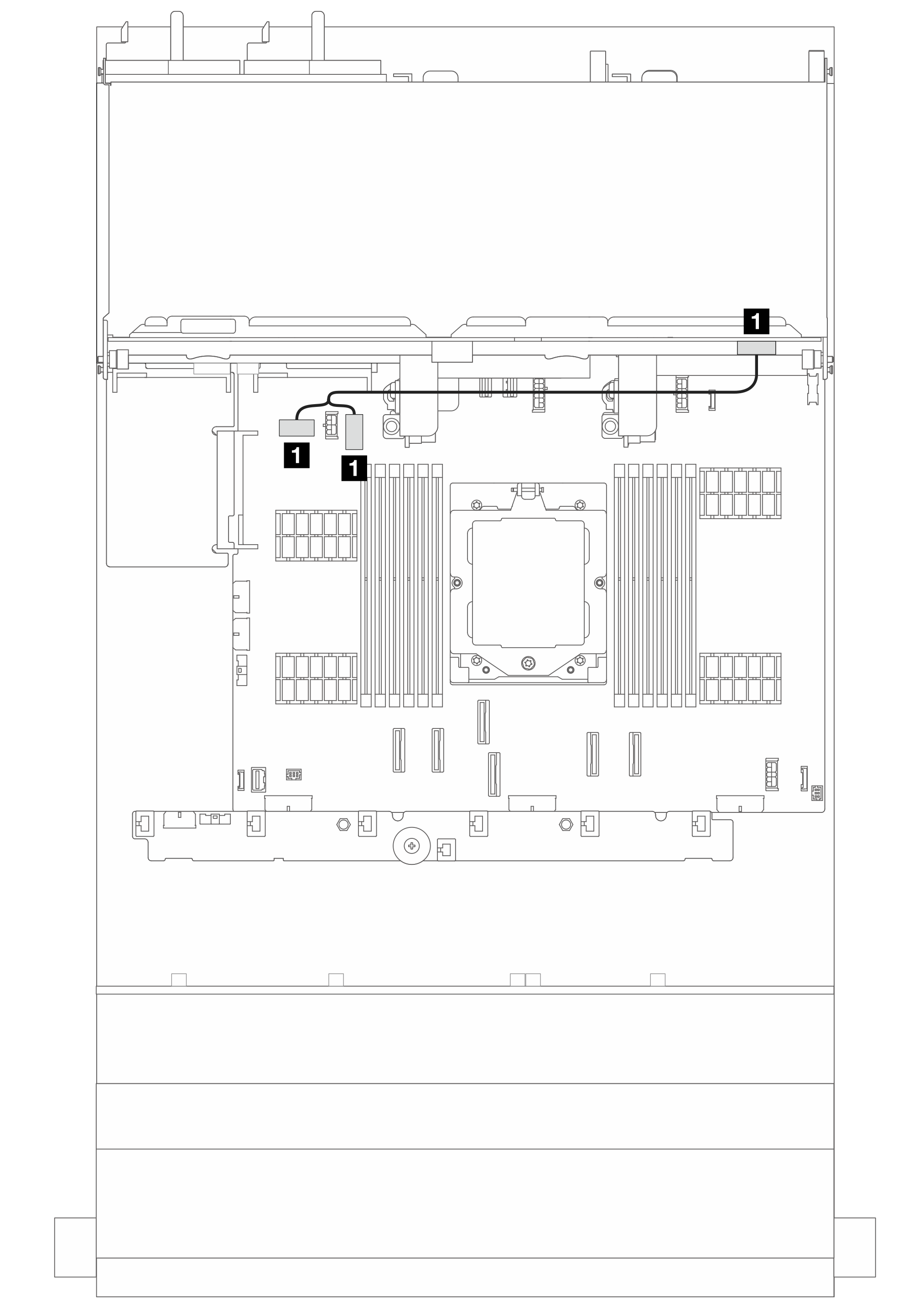
| From | To |
|---|---|
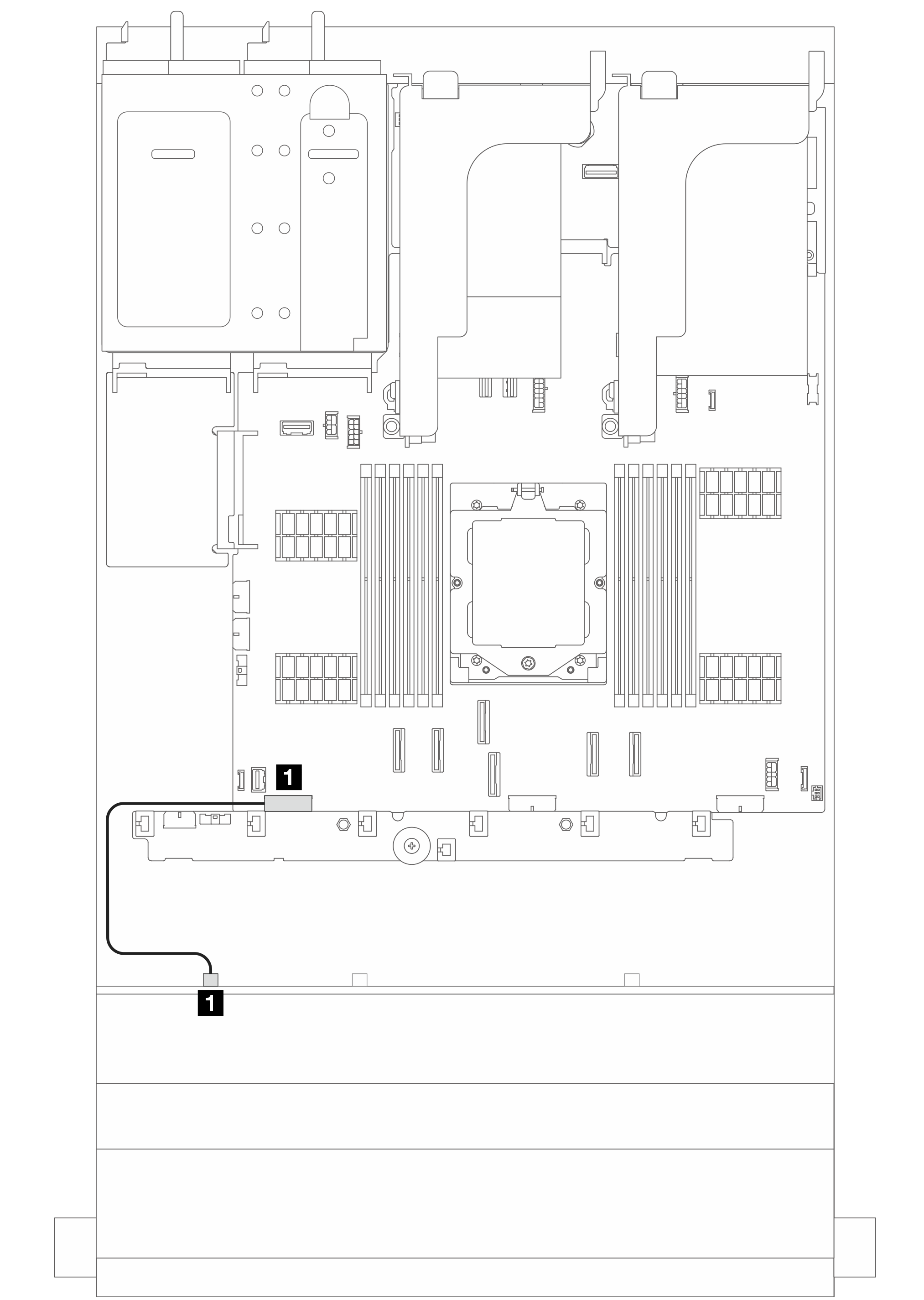
| 1 Power connector on the backplane | 1 Backplane 1 power connector on the system board assembly |
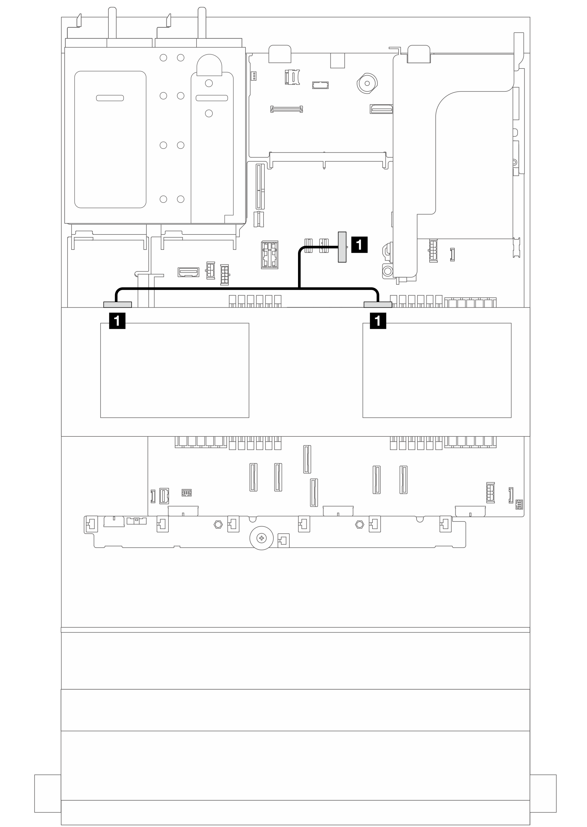
| From | To |
|---|---|
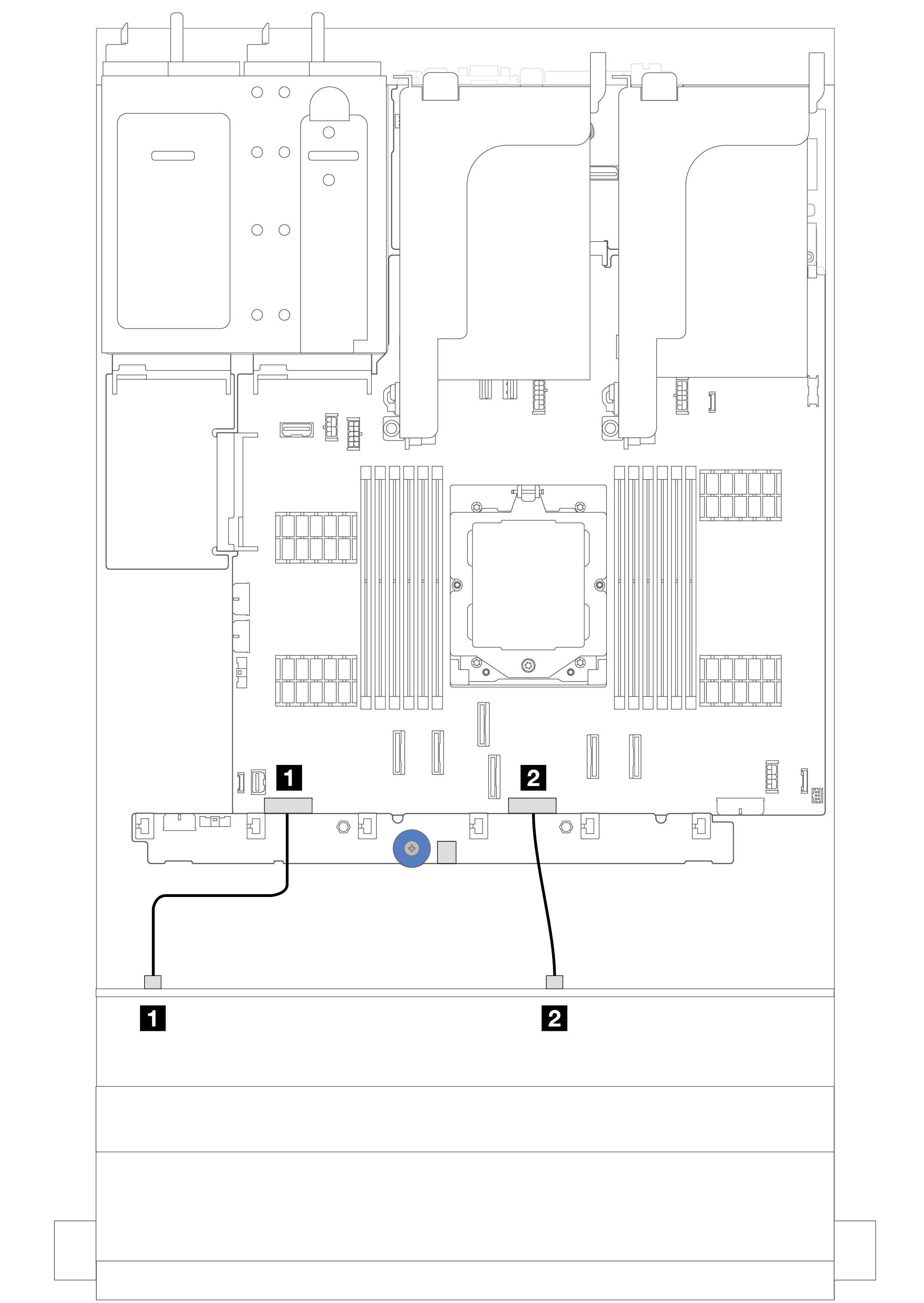
| 1 Power connector 1 on the backplane | 1 Backplane 1 power connector on the system board assembly |
| 2 Power connector 2 on the backplane | 2 Backplane 2 power connector on the system board assembly |
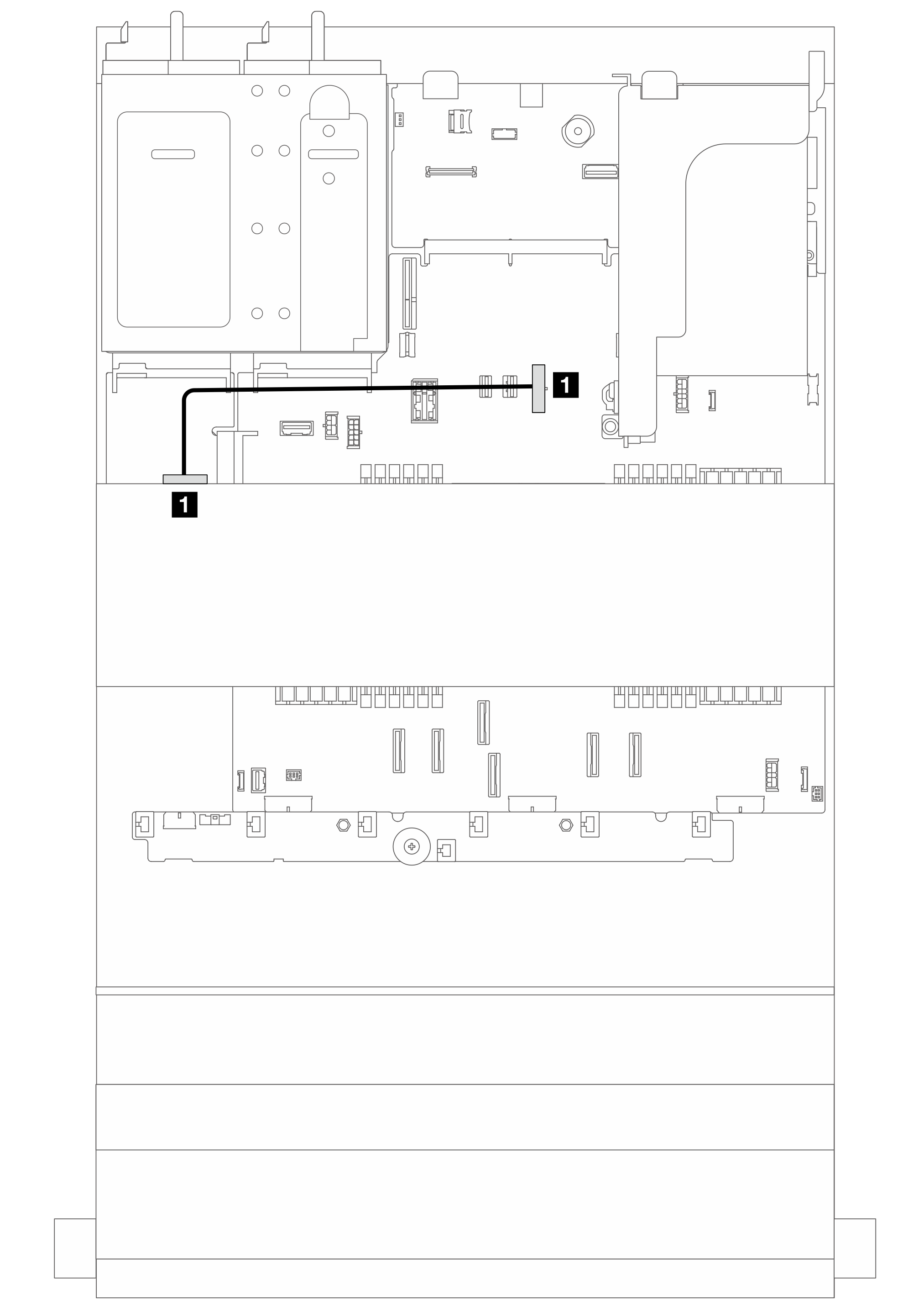
| From | To |
|---|---|
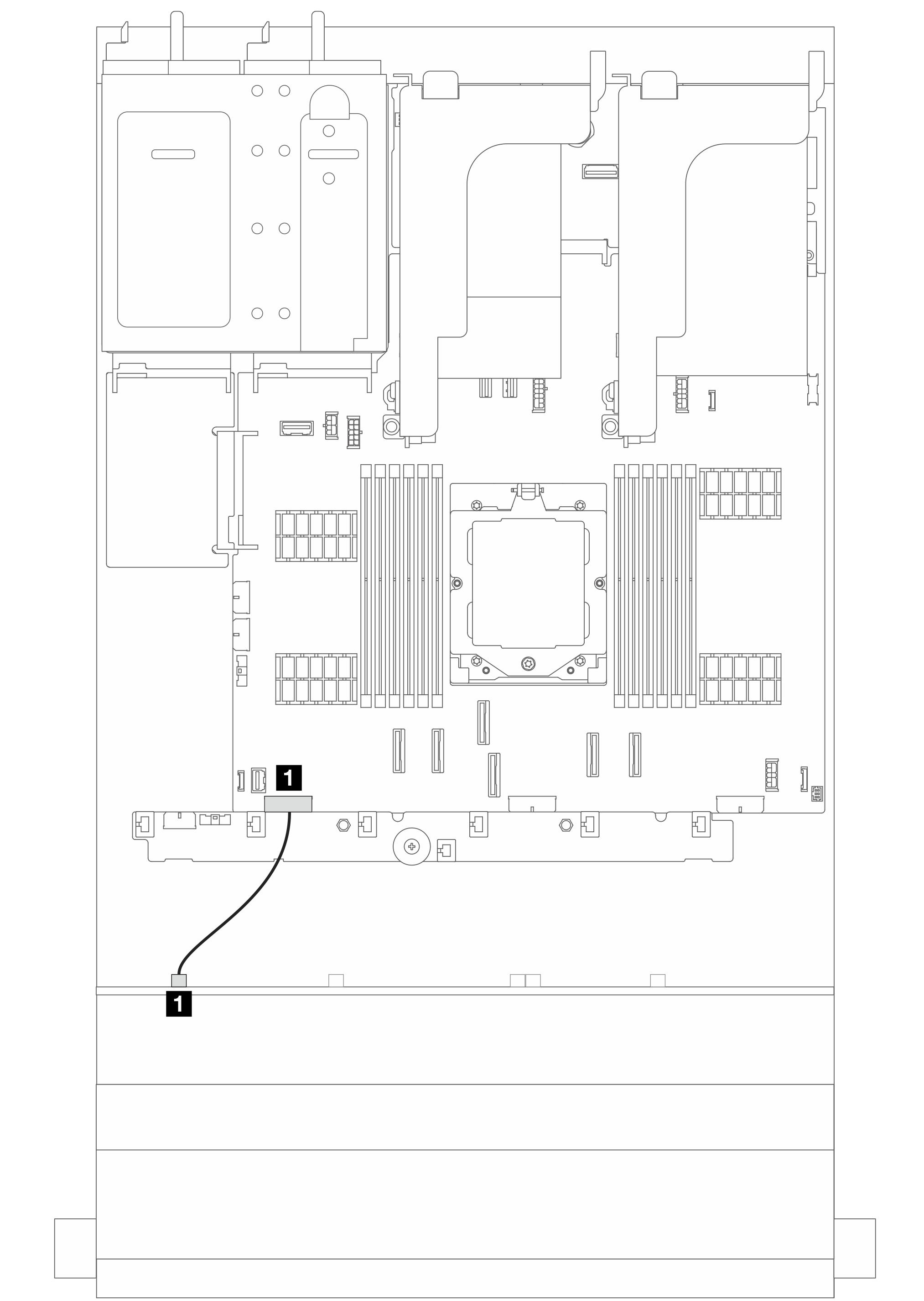
| 1 Power connector on the backplane | 1 Backplane 1 power connector on the system board assembly |
| From | To |
|---|---|
| 1 Power connector on the backplane | 1 Rear backplane power connector and sideband connector on the system board assembly |
| From | To |
|---|---|
| 1 Power connector on the backplane | 1 Rear backplane power connector and sideband connector on the system board assembly |
| From | To |
|---|---|
| 1 Power connector on the backplane | 1 Middle backplane power connector on the system board assembly |
| From | To |
|---|---|
| 1 Power connectors on the backplanes | 1 Middle backplane power connector on the system board assembly |
Signal cable connections
Refer to the specific topic for signal cable connections depending on the backplane installed.