Remove the front I/O module
Follow instructions in this section to remove the front I/O module.
About this task
Read Installation Guidelines and Safety inspection checklist to ensure that you work safely.
Power off the server and peripheral devices and disconnect the power cords and all external cables. See Power off the server.
If the server is installed in a rack, slide the server out on its rack slide rails to gain access to the top cover, or remove the server from the rack. See Remove the server from rack.
Procedure
- Disconnect all three cables of the front I/O module from their respective connectors on the system board—VGA cable connector is 7, USB cable connector is 9, and LCD diagnostic handset cable connector is 27 specified in System-board connectors.
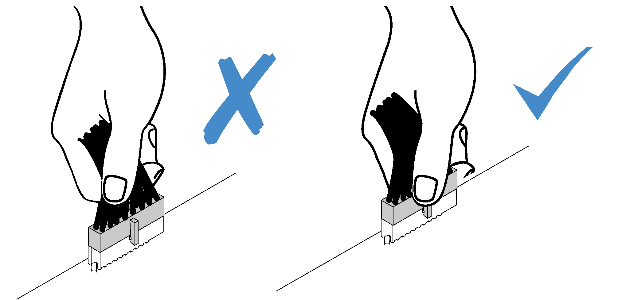
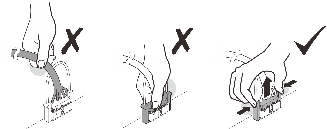
 Press release tab(s) to release the connector.
 Disengage the connector from the cable socket.Note
If there is insufficient space to press both tabs, use the provided loop to pull up and disengage the tabs on both sides.
Failing to release the tab before removing the cables will damage the cable sockets on the system board. Any damage to the cable sockets will require replacing the system board.
Figure 1. Disconnecting Front USB cable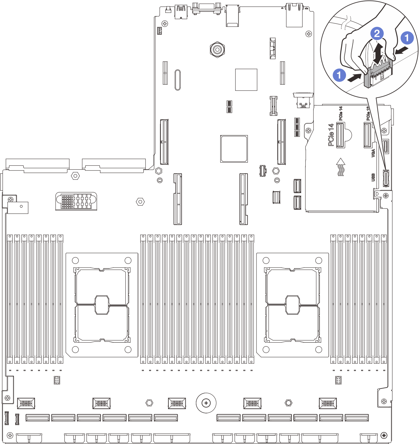 Figure 2. Disconnecting LCD diagnostic handset cable
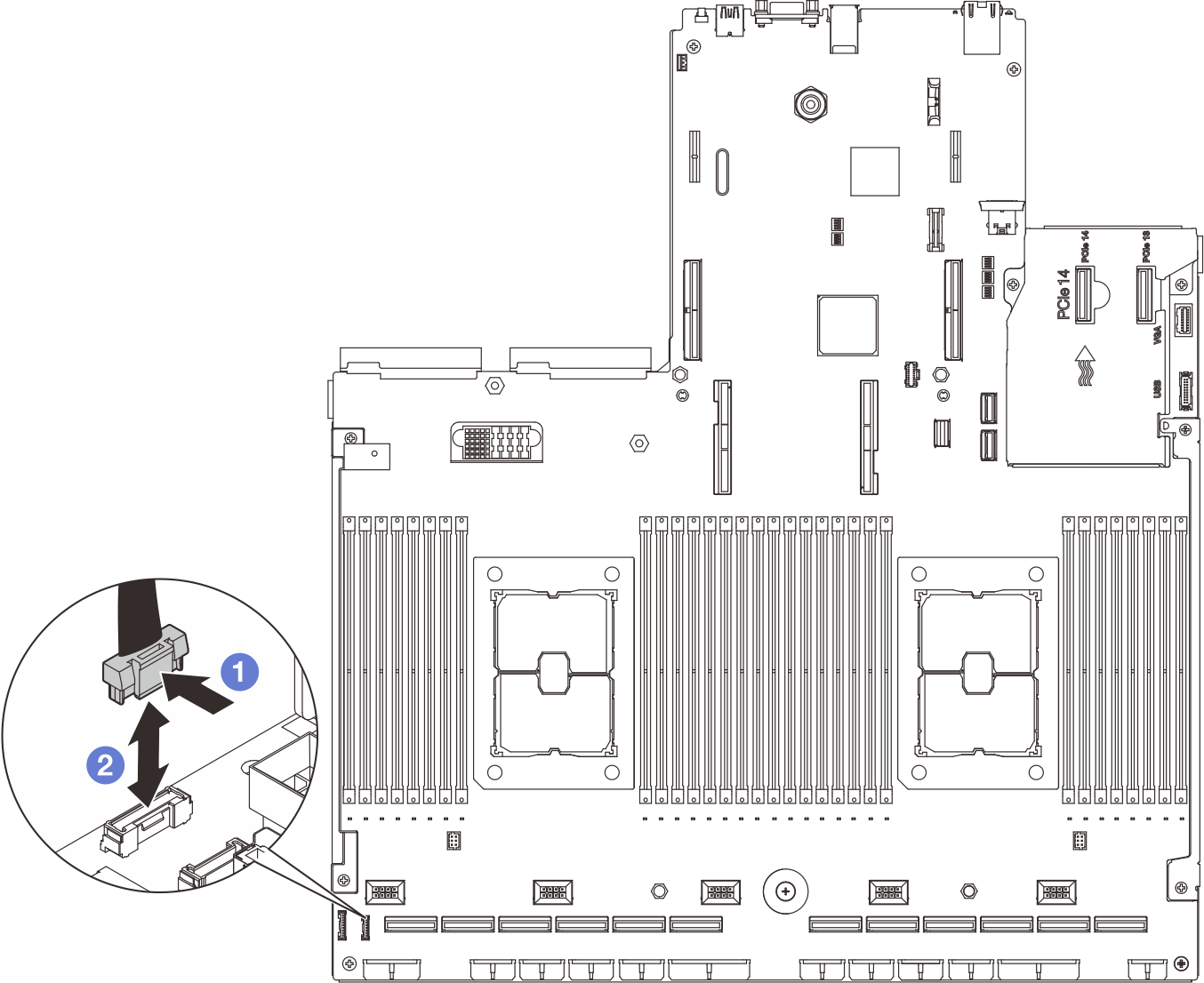
- Remove the front I/O module.
- Remove the front I/O module retention screw.
- Lift the front I/O module out of the chassis.
Figure 3. Removing the front I/O module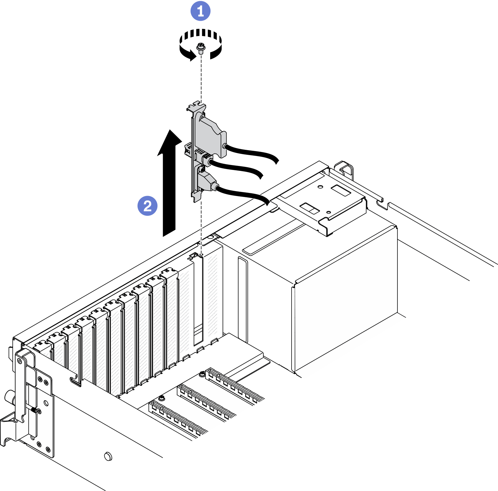
After you finish
Install a replacement unit or a slot bracket. See Install the front I/O module.
If you are instructed to return the component or optional device, follow all packaging instructions, and use any packaging materials for shipping that are supplied to you.
Demo video