DRAM installation order
Memory modules must be installed in a specific order based on the memory configuration that you implement on your node.
The following memory configurations are available:
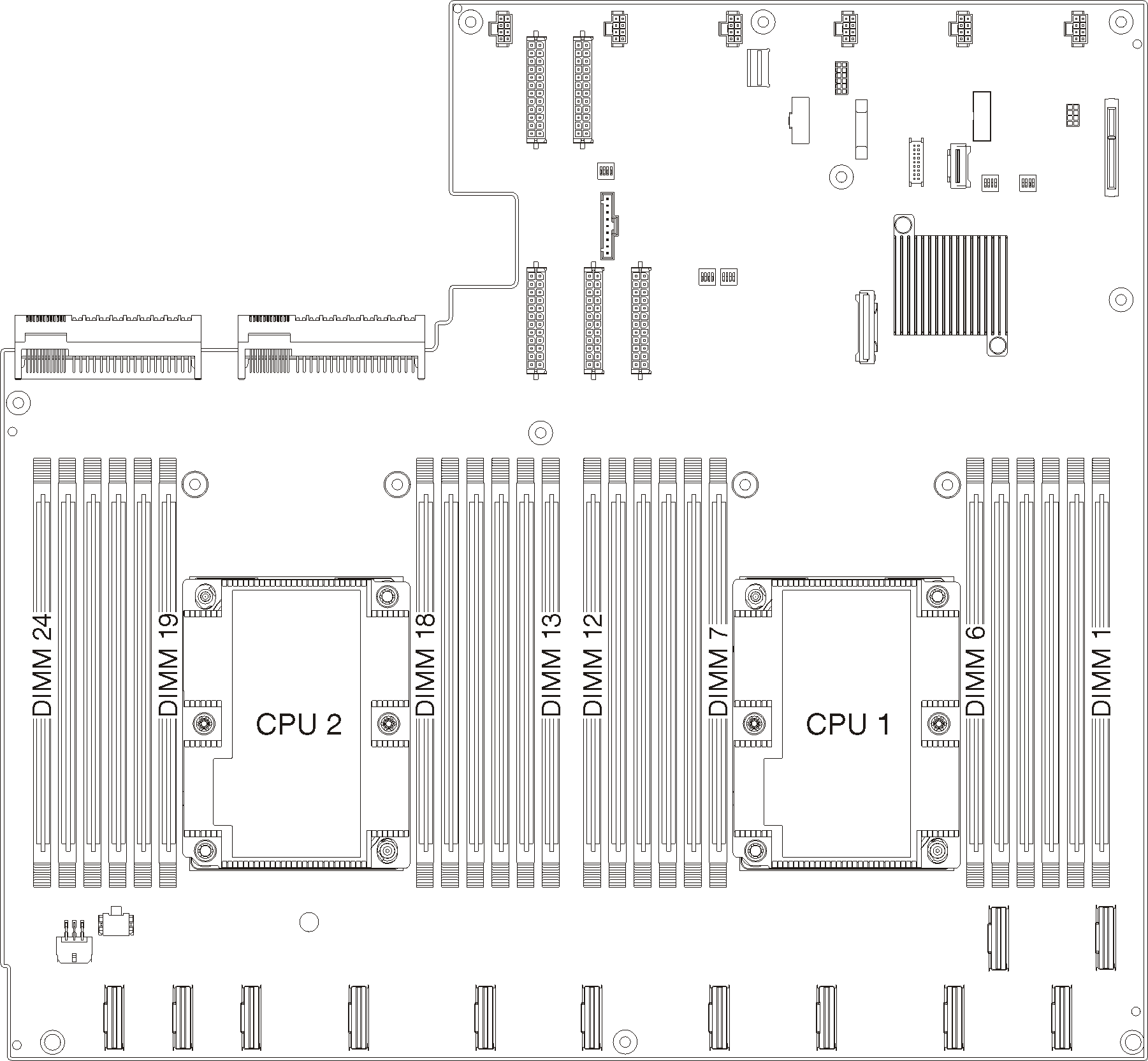
The following illustration shows the location of the DIMM connectors on the system board.
Figure 1. The location of the DIMM connectors on the system board


Independent mode
The independent mode provides high performance memory capability. You can populate all channels with no matching requirements. Individual channels can run at different memory module timings, but all channels must run at the same interface frequency.
Note
All memory modules installed on Product_name must be the same type with the same capacity, frequency, voltage, and ranks.
The following table shows the memory module population sequence for the independent mode when two processors (Processor 1 and Processor 2) are installed.
| Independent memory mode | |||||||||||||||||||||||||||
|---|---|---|---|---|---|---|---|---|---|---|---|---|---|---|---|---|---|---|---|---|---|---|---|---|---|---|---|
| Total DIMMs | Processor 1 | Processor 2 | |||||||||||||||||||||||||
| DIMM slot | DIMM slot | ||||||||||||||||||||||||||
| 1 | 2 | 3 | 4 | 5 | 6 | 7 | 8 | 9 | 10 | 11 | 12 | 13 | 14 | 15 | 16 | 17 | 18 | 19 | 20 | 21 | 22 | 23 | 24 | ||||
| 8 | √ | √ | √ | √ | √ | √ | √ | √ | |||||||||||||||||||
| 12 | √ | √ | √ | √ | √ | √ | √ | √ | √ | √ | √ | √ | |||||||||||||||
| 16 | √ | √ | √ | √ | √ | √ | √ | √ | √ | √ | √ | √ | √ | √ | √ | √ | |||||||||||
| 24 | √ | √ | √ | √ | √ | √ | √ | √ | √ | √ | √ | √ | √ | √ | √ | √ | √ | √ | √ | √ | √ | √ | √ | √ | |||
Mirroring mode
In the mirroring mode, each memory module in a pair must be identical in size and architecture. The channels are grouped in pairs with each channel receiving the same data. One channel is used as a backup of the other, which provides redundancy.
Note
All memory modules installed on Product_name must be the same type with the same capacity, frequency, voltage, and ranks.
The following table shows the memory module population sequence for the mirroring mode when two processors (Processor 1 and Processor 2) are installed.
| Mirroring mode | |||||||||||||||||||||||||||
|---|---|---|---|---|---|---|---|---|---|---|---|---|---|---|---|---|---|---|---|---|---|---|---|---|---|---|---|
| Total DIMMs | Processor 1 | Processor 2 | |||||||||||||||||||||||||
| DIMM slot | DIMM slot | ||||||||||||||||||||||||||
| 1 | 2 | 3 | 4 | 5 | 6 | 7 | 8 | 9 | 10 | 11 | 12 | 13 | 14 | 15 | 16 | 17 | 18 | 19 | 20 | 21 | 22 | 23 | 24 | ||||
| 8 | √ | √ | √ | √ | √ | √ | √ | √ | |||||||||||||||||||
| 12 | √ | √ | √ | √ | √ | √ | √ | √ | √ | √ | √ | √ | |||||||||||||||
| 16 | √ | √ | √ | √ | √ | √ | √ | √ | √ | √ | √ | √ | √ | √ | √ | √ | |||||||||||
| 24 | √ | √ | √ | √ | √ | √ | √ | √ | √ | √ | √ | √ | √ | √ | √ | √ | √ | √ | √ | √ | √ | √ | √ | √ | |||
Rank sparing mode
In the rank sparing mode, one rank of a memory module works as the spare rank for the other ranks on the same channel. The spare rank is not available as system memory.
Note
All memory modules installed on Product_name must be the same type with the same capacity, frequency, voltage, and ranks.
The following table shows the memory module population sequence for the rank sparing mode when two processors (Processor 1 and Processor 2) are installed.
| Rank sparing mode | |||||||||||||||||||||||||||
|---|---|---|---|---|---|---|---|---|---|---|---|---|---|---|---|---|---|---|---|---|---|---|---|---|---|---|---|
| Total DIMMs | Processor 1 | Processor 2 | |||||||||||||||||||||||||
| DIMM slot | DIMM slot | ||||||||||||||||||||||||||
| 1 | 2 | 3 | 4 | 5 | 6 | 7 | 8 | 9 | 10 | 11 | 12 | 13 | 14 | 15 | 16 | 17 | 18 | 19 | 20 | 21 | 22 | 23 | 24 | ||||
| 8 | √ | √ | √ | √ | √ | √ | √ | √ | |||||||||||||||||||
| 12 | √ | √ | √ | √ | √ | √ | √ | √ | √ | √ | √ | √ | |||||||||||||||
| 16 | √ | √ | √ | √ | √ | √ | √ | √ | √ | √ | √ | √ | √ | √ | √ | √ | |||||||||||
| 24 | √ | √ | √ | √ | √ | √ | √ | √ | √ | √ | √ | √ | √ | √ | √ | √ | √ | √ | √ | √ | √ | √ | √ | √ | |||
Give documentation feedback