System-board-assembly switches
The following illustration shows the location of the switches, jumpers, and buttons on the system board assembly.
Note
If there is a clear protective sticker on the top of the switch blocks, you must remove and discard it to access the switches.
Figure 1. System-board-assembly switches
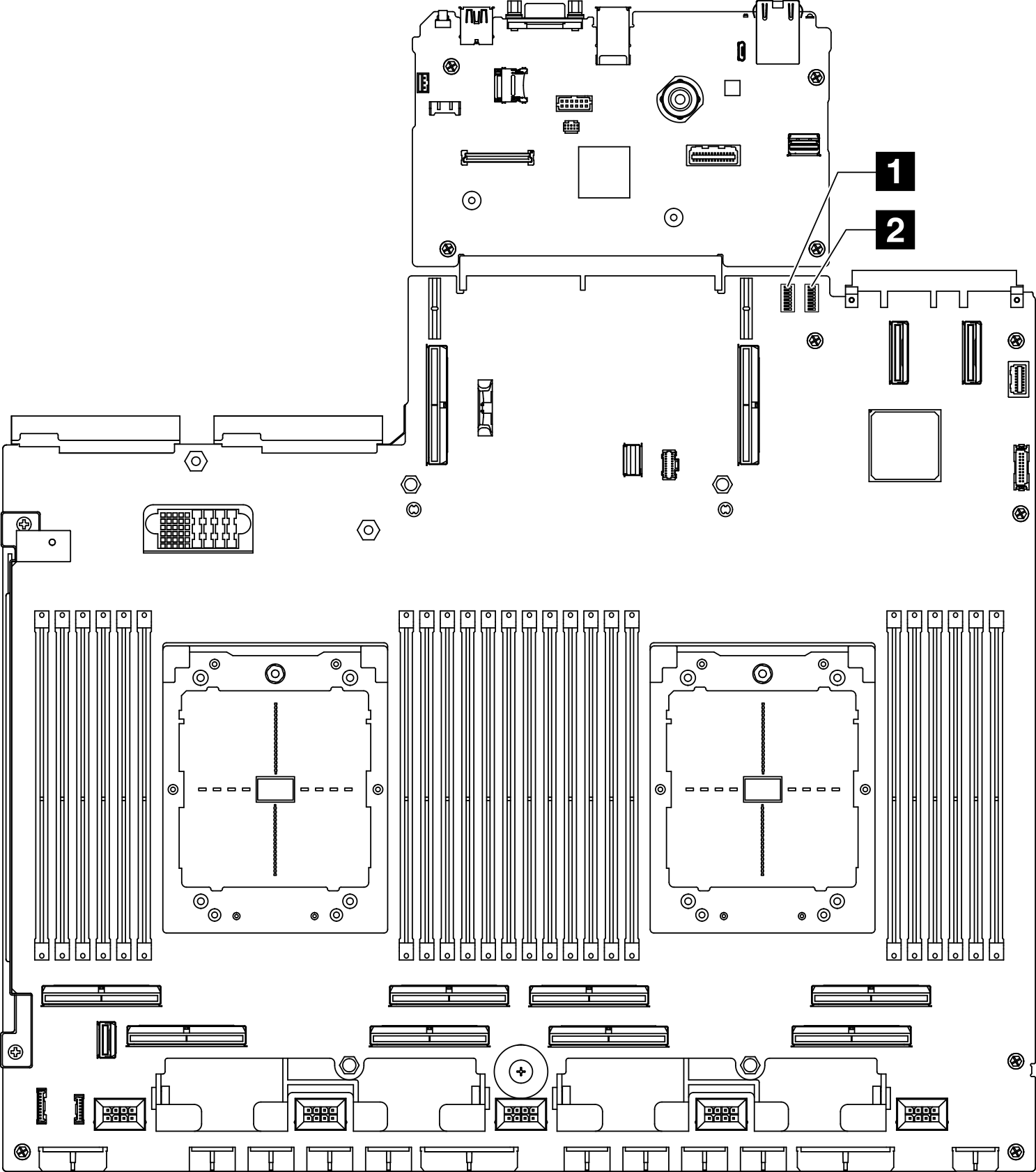
| 1 Switch block 6 (SW6) | 2 Switch block 5 (SW5) |
Important
Before you change any switch settings or move any jumpers, turn off the server; then, disconnect all power cords and external cables. Review the following information:
- Any system-board-assembly switch or jumper block that is not shown in the illustrations in this document are reserved.
Switch block 6 (SW6)
The following table describes the functions of the switch block 6 (SW6) on the system board assembly.
| Switch number | Default position | Description |
|---|---|---|
| 1 | Off | Reserved |
| 2 | Off | Reserved |
| 3 | Off | Reserved |
| 4 | Off | Reserved |
| 5 | Off | Reserved |
| 6 | Off | Reserved |
| 7 | Off | Reserved |
| 8 | Off | Reserved |
Switch block 5 (SW5)
The following table describes the functions of the switch block 5 (SW5) on the system board assembly.
| Switch number | Default position | Description |
|---|---|---|
| 1 | Off | Changing this switch to the On position forces the XCC processor into reset. |
| 2 | Off | Changing this switch to the On position forces the real time clock to reset. |
| 3 | Off | Changing this switch to the On position provides one time Power-On password bypass. |
| 4 | Off | Changing this switch to the On position forces FPGA into reset. |
| 5 | Off | Reserved |
| 6 | Off | Reserved |
| 7 | Off | Reserved |
| 8 | Off | Reserved |
Give documentation feedback