Rear view
The rear of the server provides access to several components, including the power supplies, PCIe adapters, serial port, and Ethernet port.
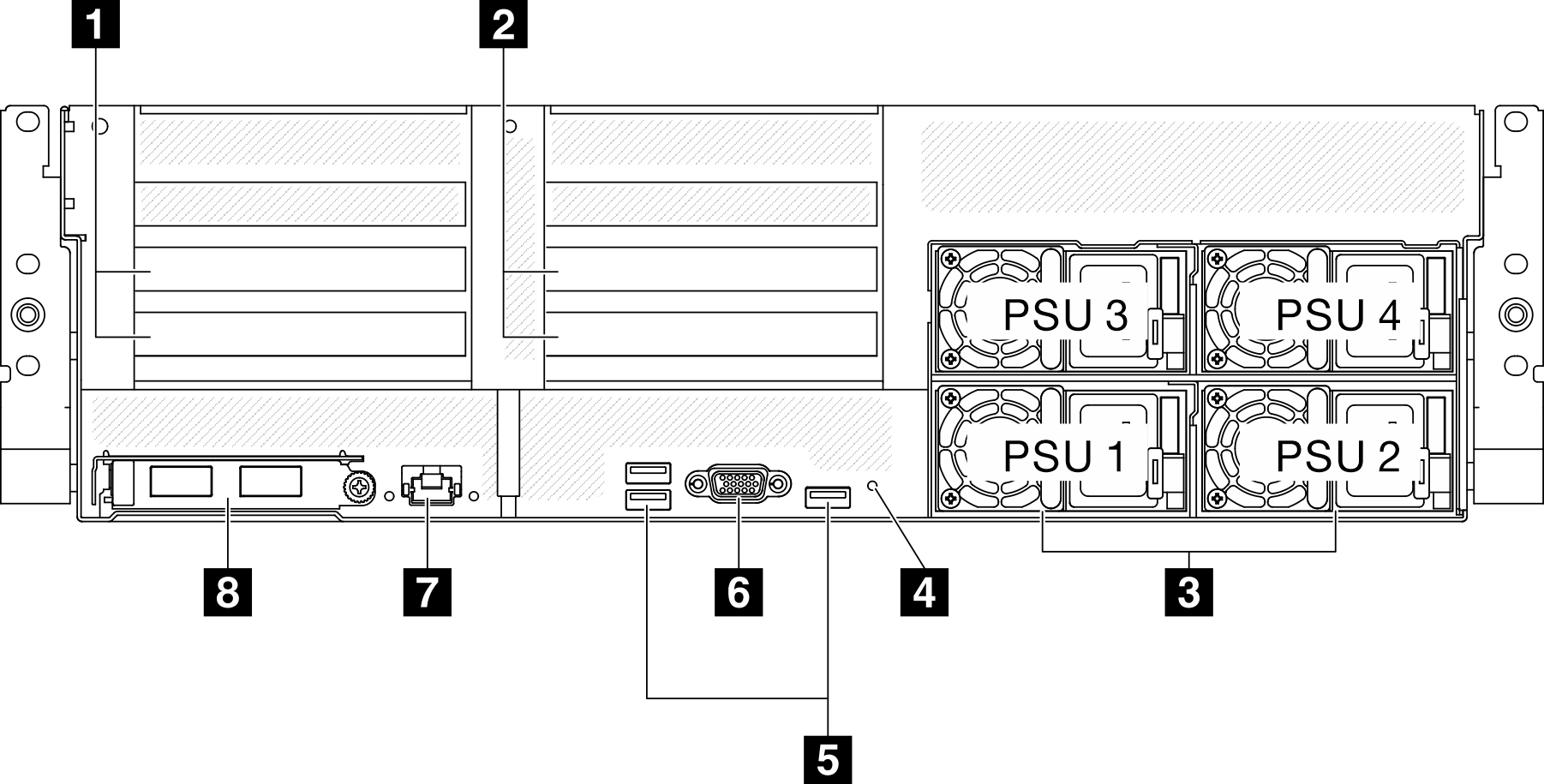
| 1 PCIe riser 1 (PCIe slot 15-16) | 5 USB 3.2 Gen 1 (5 Gbps) connectors (total of three connectors) |
| 2 PCIe riser 2 (PCIe slot 20-21) | 6 VGA connector |
| 3 Power supply units | 7 XCC system management port (1 GB RJ-45) |
| 4 NMI button | 8 OCP module (slot 27) |
1 PCIe riser 1 (PCIe slot 15-16)
- PCIe x16 75W, FH/HL
2 PCIe riser 2 (PCIe slot 20-21)
- PCIe x16 75W, FH/HL
3 Power supply units
Install power supply units to these bays, connect them to power cords. Make sure the power cords are connected properly. Following are the power supplies supported by this system:
- 1800-watt Platinum, input voltage 230 Vac
- 1800-watt Titanium, input voltage 230 Vac
- 2400-watt Platinum, input voltage 230 Vac
- 2600-watt Titanium, input voltage 230 Vac
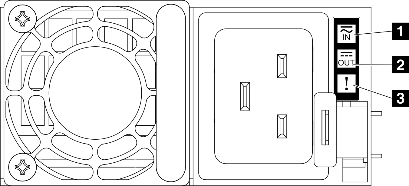
| LED | Description |
|---|---|
| 1 Input status | The input status LED can be in one of the following states:
|
| 2 Output status | The output status LED can be in one of the following states:
|
| 3 Fault LED |
|
5 USB 3.2 Gen 1 (5 Gbps) connectors
There are three USB 3.2 Gen 1 (5 Gbps) connectors on the rear of the server. Connect a USB device, such as a mouse, keyboard, or other devices, to either of these connectors.
6 VGA connector
Connect a monitor to this connector.
7 XCC system management port (1 GB RJ-45)
The server has a 1 GB RJ-45 connector dedicated to Lenovo XClarity Controller (XCC) functions. Through the system management port, you can access the Lenovo XClarity Controller directly by connecting your laptop to the management port using an Ethernet cable. Make sure that you modify the IP settings on the laptop so that it is on the same network as the server default settings. A dedicated management network provides additional security by physically separating the management network traffic from the production network.
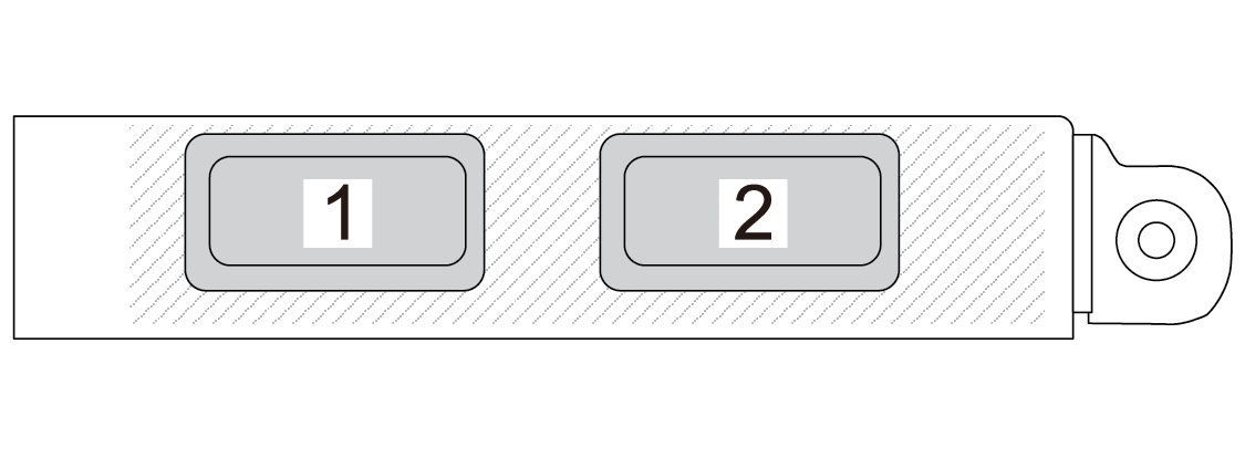
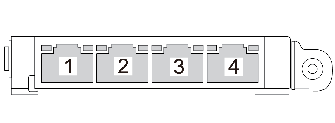
8 OCP module (slot 27)