The SXM5 GPU Model front view
This section contains information about the controls, LEDs, and connectors on the front of the SXM5 GPU Model server.
Front view with 4x 2.5-inch drives and SXM5 PCIe switch board
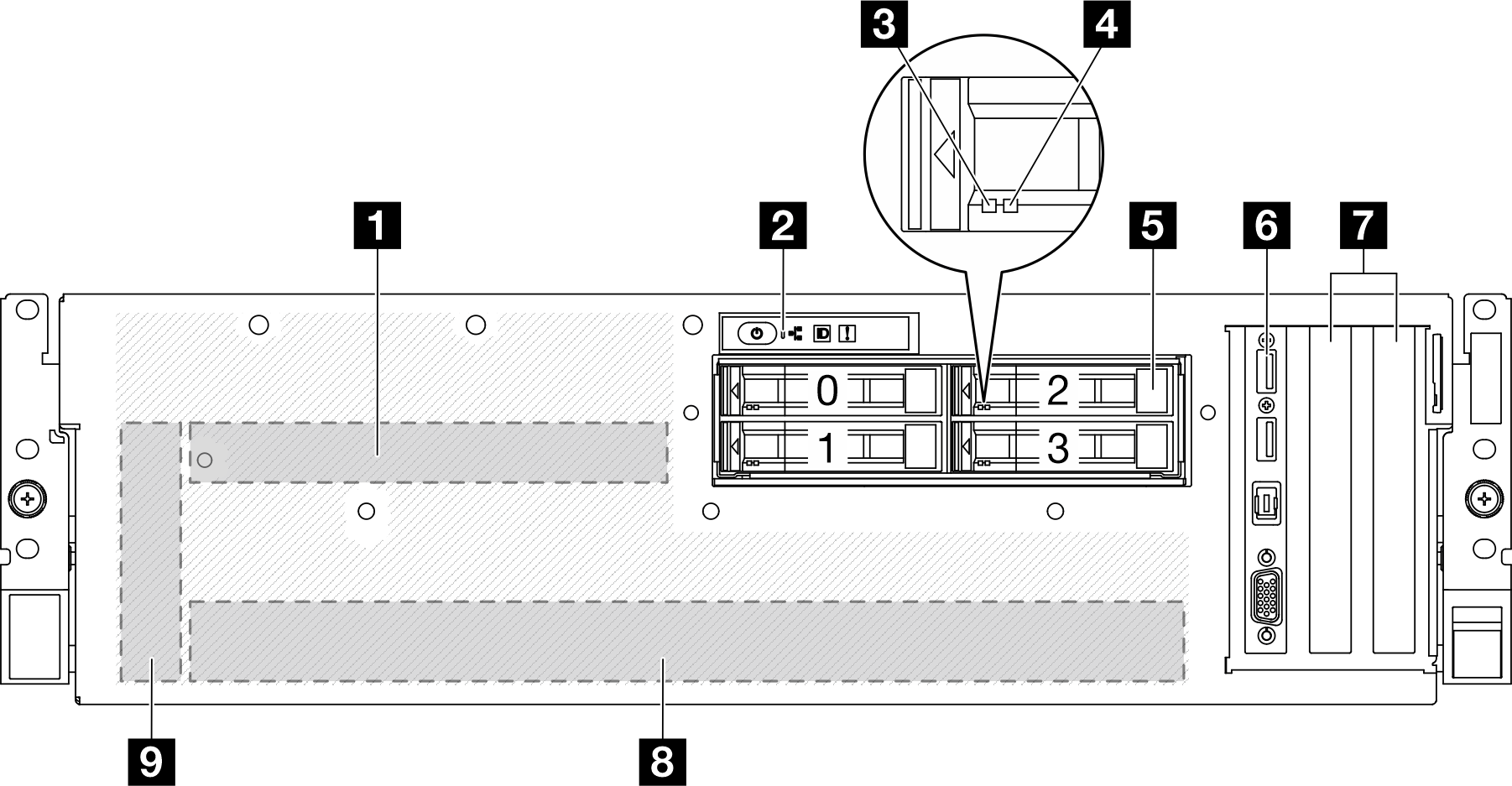
| 1 SXM5 PCIe switch board | 6 Front I/O module |
| 2 Front operator panel | 7 PCIe Slot 1-2 |
| 3 Drive activity LED (green) | 8 GPU-L2A assembly |
| 4 Drive status LED (yellow) | 9 Interposer card |
| 5 2.5-inch hot-swap drive bays (0 to 3) |
1 SXM5 PCIe switch board
Install the SXM5 PCIe switch board in this space. See Install the SXM5 PCIe switch board for more information.
2 Front operator panel
For more information about the front operator panel, see Front operator panel LEDs.
3 Drive activity LED (green)
Each hot-swap drive comes with an activity LED. When this LED is flashing, it indicates that the drive is in use.
4 Drive status LED (yellow)
- The LED is lit: the drive has failed.
- The LED is flashing slowly (once per second): the drive is being rebuilt.
- The LED is flashing rapidly (three times per second): the drive is being identified.
5 2.5-inch hot-swap drive bays (0 to 3)
Install 2.5-inch drives to these bays. See Install a 2.5-inch hot-swap drive for more information.
6 Front I/O module
For more information about the front I/O module, see Front I/O module.
7 PCIe Slot 1-2
- PCIe Gen5 x16, FH/HL
8 GPU-L2A assembly
Install the GPU-L2A assembly in this space. A GPU-L2A assembly consists of the Lenovo Neptune® liquid-to-air (L2A) hybrid cooling module and the SXM5 GPU board which contains one set of NVIDIA HGX H100 80GB 700W 4-GPU Board. See Install the Lenovo Neptune liquid-to-air (L2A) hybrid cooling module for more information.
9 Interposer card
Install the interposer card in this space. See Install the interposer card for more information.
Front view with 4x 2.5-inch drives and CX-7 mezz board
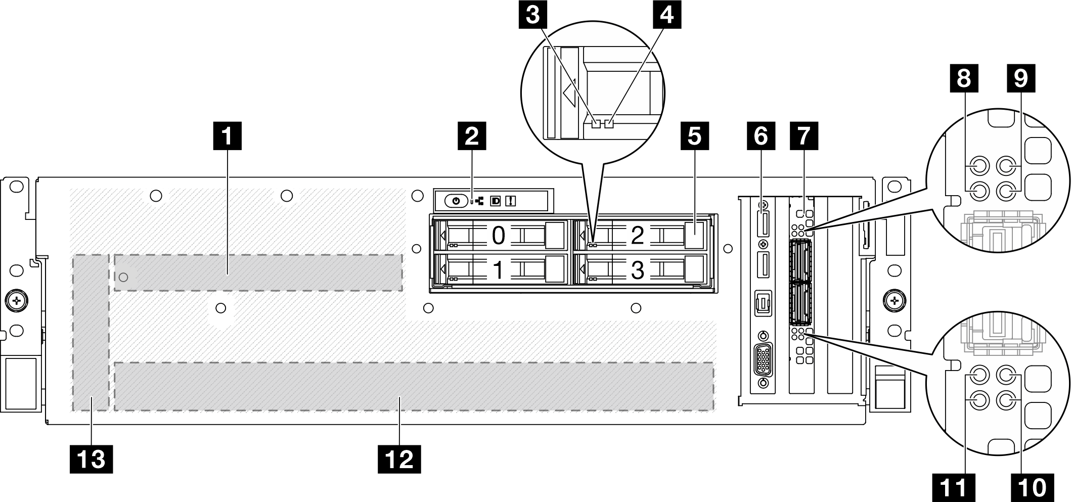
| 1 CX-7 mezz board | 8 CX-7 mezz board link status LED (yellow) |
| 2 Front operator panel | 9 CX-7 mezz board link activity LED (green) |
| 3 Drive activity LED (green) | 10 CX-7 mezz board link activity LED (green) |
| 4 Drive status LED (yellow) | 11 CX-7 mezz board link status LED (yellow) |
| 5 2.5-inch hot-swap drive bays (0 to 3) | 12 GPU-L2A assembly |
| 6 Front I/O module | 13 Interposer card |
| 7 OSFP port card |
1 CX-7 mezz board
Install the CX-7 mezz board in this space. See Install the CX-7 carrier board and CX-7 mezz board for more information.
2 Front operator panel
For more information about the front operator panel, see Front operator panel LEDs.
3 Drive activity LED (green)
Each hot-swap drive comes with an activity LED. When this LED is flashing, it indicates that the drive is in use.
4 Drive status LED (yellow)
- The LED is lit: the drive has failed.
- The LED is flashing slowly (once per second): the drive is being rebuilt.
- The LED is flashing rapidly (three times per second): the drive is being identified.
5 2.5-inch hot-swap drive bays (0 to 3)
Install 2.5-inch drives to these bays. See Install a 2.5-inch hot-swap drive for more information.
6 Front I/O module
For more information about the front I/O module, see Front I/O module.
7 OSFP port card
Install the OSFP port card in this space. See Install the OSFP port card for more information.
8/11 CX-7 mezz board link status LED (yellow)
- For one-processor configuration: from top to bottom, these LEDs represent ConnectX-7 chip sets 0, 1, 2, and 3.
- For two-processor configuration: from top to bottom, these LEDs represent ConnectX-7 chip sets 0, 1, 2, and 3.
- Off: The network is disconnected from switch.
- Blinking (1 Hz): The beacon command is used to locate the OSFP port card.
- Blinking (4 Hz): An error has occurred to the link. The error can be from I2C or overcurrent.
- On: A physical network link is detected.
9/10 CX-7 mezz board link activity LED (green)
- For one-processor configuration: from top to bottom, these LEDs represent ConnectX-7 chip sets 0, 1, 2, and 3.
- For two-processor configuration: from top to bottom, these LEDs represent ConnectX-7 chip sets 0, 1, 2, and 3.
- Off: The network is disconnected from switch.
- Blinking: The network link is connected and active.
- On: The network link is connected with no active traffic.
12 GPU-L2A assembly
Install the GPU-L2A assembly in this space. A GPU-L2A assembly consists of the Lenovo Neptune® liquid-to-air (L2A) hybrid cooling module and the SXM5 GPU board which contains one set of NVIDIA HGX H100 80GB 700W 4-GPU Board. See Install the Lenovo Neptune liquid-to-air (L2A) hybrid cooling module for more information.
13 Interposer card
Install the interposer card in this space. See Install the interposer card for more information.
Front view with 4x E3.S 1T drives and SXM5 PCIe switch board
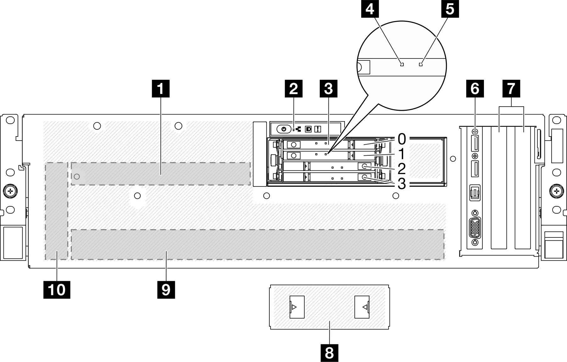
| 1 SXM5 PCIe switch board | 6 Front I/O module |
| 2 Front operator panel | 7 PCIe Slot 1-2 |
| 3 E3.S 1T hot-swap drive bays (0 to 3) | 8 E3.S drive cage cover |
| 4 Drive activity LED (green) | 9 GPU-L2A assembly |
| 5 Drive status LED (yellow) | 10 Interposer card |
1 SXM5 PCIe switch board
Install the SXM5 PCIe switch board in this space. See Install the SXM5 PCIe switch board for more information.
2 Front operator panel
For more information about the front operator panel, see Front operator panel LEDs.
3 E3.S 1T hot-swap drive bays (0 to 3)
Install E3.S 1T drives to these bays. See Install an E3.S hot-swap drive for more information.
4 Drive activity LED (green)
Each hot-swap drive comes with an activity LED. When this LED is flashing, it indicates that the drive is in use.
5 Drive status LED (yellow)
- The LED is lit: the drive has failed.
- The LED is flashing slowly (once per second): the drive is being rebuilt.
- The LED is flashing rapidly (three times per second): the drive is being identified.
6 Front I/O module
For more information about the front I/O module, see Front I/O module.
7 PCIe Slot 1-2
- PCIe Gen5 x16, FH/HL
8 E3.S drive cage cover
The SXM5 GPU Model with 4x E3.S 1T drives should always operate with the E3.S drive cage cover installed to the chassis.
9 GPU-L2A assembly
Install the GPU-L2A assembly in this space. A GPU-L2A assembly consists of the Lenovo Neptune® liquid-to-air (L2A) hybrid cooling module and the SXM5 GPU board which contains one set of NVIDIA HGX H100 80GB 700W 4-GPU Board. See Install the Lenovo Neptune liquid-to-air (L2A) hybrid cooling module for more information.
10 Interposer card
Install the interposer card in this space. See Install the interposer card for more information.
Front view with 4x E3.S 1T drives and CX-7 mezz board
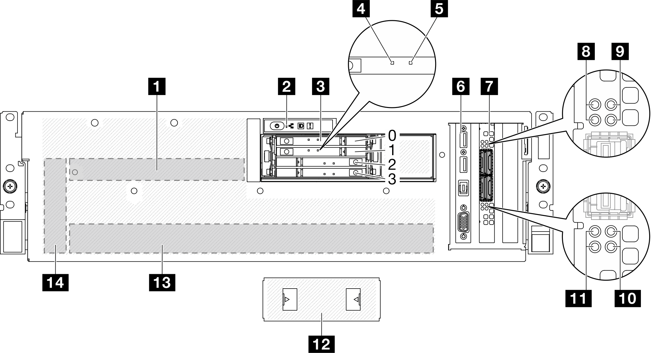
| 1 CX-7 mezz board | 8 CX-7 mezz board link status LED (yellow) |
| 2 Front operator panel | 9 CX-7 mezz board link activity LED (green) |
| 3 E3.S 1T hot-swap drive bays (0 to 3) | 10 CX-7 mezz board link activity LED (green) |
| 4 Drive activity LED (green) | 11 CX-7 mezz board link status LED (yellow) |
| 5 Drive status LED (yellow) | 12 E3.S drive cage cover |
| 6 Front I/O module | 13 GPU-L2A assembly |
| 7 OSFP port card | 14 Interposer card |
1 CX-7 mezz board
Install the CX-7 mezz board in this space. See Install the CX-7 carrier board and CX-7 mezz board for more information.
2 Front operator panel
For more information about the front operator panel, see Front operator panel LEDs.
3 E3.S 1T hot-swap drive bays (0 to 3)
Install E3.S 1T drives to these bays. See Install an E3.S hot-swap drive for more information.
4 Drive activity LED (green)
Each hot-swap drive comes with an activity LED. When this LED is flashing, it indicates that the drive is in use.
5 Drive status LED (yellow)
- The LED is lit: the drive has failed.
- The LED is flashing slowly (once per second): the drive is being rebuilt.
- The LED is flashing rapidly (three times per second): the drive is being identified.
6 Front I/O module
For more information about the front I/O module, see Front I/O module.
7 OSFP port card
Install the OSFP port card in this space. See Install the OSFP port card for more information.
8/11 CX-7 mezz board link status LED (yellow)
- For one-processor configuration: from top to bottom, these LEDs represent ConnectX-7 chip sets 0, 1, 2, and 3.
- For two-processor configuration: from top to bottom, these LEDs represent ConnectX-7 chip sets 0, 1, 2, and 3.
- Off: The network is disconnected from switch.
- Blinking (1 Hz): The beacon command is used to locate the OSFP port card.
- Blinking (4 Hz): An error has occurred to the link. The error can be from I2C or overcurrent.
- On: A physical network link is detected.
9/10 CX-7 mezz board link activity LED (green)
- For one-processor configuration: from top to bottom, these LEDs represent ConnectX-7 chip sets 0, 1, 2, and 3.
- For two-processor configuration: from top to bottom, these LEDs represent ConnectX-7 chip sets 0, 1, 2, and 3.
- Off: The network is disconnected from switch.
- Blinking: The network link is connected and active.
- On: The network link is connected with no active traffic.
12 E3.S drive cage cover
The SXM5 GPU Model with 4x E3.S 1T drives should always operate with the E3.S drive cage cover installed to the chassis.
13 GPU-L2A assembly
Install the GPU-L2A assembly in this space. A GPU-L2A assembly consists of the Lenovo Neptune® liquid-to-air (L2A) hybrid cooling module and the SXM5 GPU board which contains one set of NVIDIA HGX H100 80GB 700W 4-GPU Board. See Install the Lenovo Neptune liquid-to-air (L2A) hybrid cooling module for more information.
14 Interposer card
Install the interposer card in this space. See Install the interposer card for more information.