The 4-DW GPU Model front view
This section contains information about the controls, LEDs, and connectors on the front of the 4-DW GPU Model server.
Note
The illustration in this section show the location of certain parts. Some parts may not be supported at the same time within certain configuration(s).
Figure 1. Front view of the 4-DW GPU Model
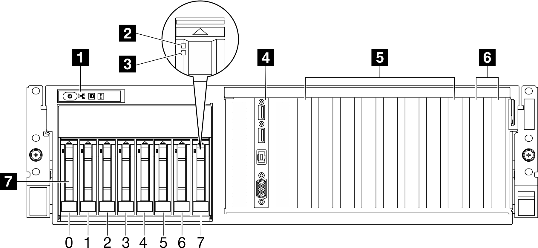
| 1 Front operator panel | 5 PCIe slot 3-6 |
| 2 Drive activity LED (green) | 6 PCIe slot 1-2 |
| 3 Drive status LED (yellow) | 7 2.5-inch hot-swap drive bays (0 to 7) |
| 4 Front I/O module |
1 Front operator panel
For more information about the front operator panel, see Front operator panel LEDs.
2 Drive activity LED (green)
Each hot-swap drive comes with an activity LED. When this LED is flashing, it indicates that the drive is in use.
3 Drive status LED (yellow)
The drive status LED indicates the following status:
- The LED is lit: the drive has failed.
- The LED is flashing slowly (once per second): the drive is being rebuilt.
- The LED is flashing rapidly (three times per second): the drive is being identified.
4 Front I/O module
For more information about the front I/O module, see Front I/O module.
5 PCIe slot 3-6
Install PCIe adapters, particularly GPUs to these slots. These PCIe slots support the following configuration:
- PCIe Gen5 x16, FH/FL
6 PCIe slot 1-2
Install PCIe adapters, particularly network adapters to these slots. These PCIe slots support the following configuration:
- PCIe Gen5 x16, FH/FL
Note
PCIe solid fillers must be installed in slots 1 and 2 if no PCIe adapter is installed in those slots.
7 2.5-inch hot-swap drive bays (0 to 7)
Install 2.5-inch drives to these bays. See Install a 2.5-inch hot-swap drive for more information.
Give documentation feedback