PCIe switch board cable routing
Use the section to understand the cable routing for the PCIe switch board.
Based on the location, select the corresponding routing plan:
In 2U compute shuttle
Signal cables
Figure 1. PCIe switch board cable routing
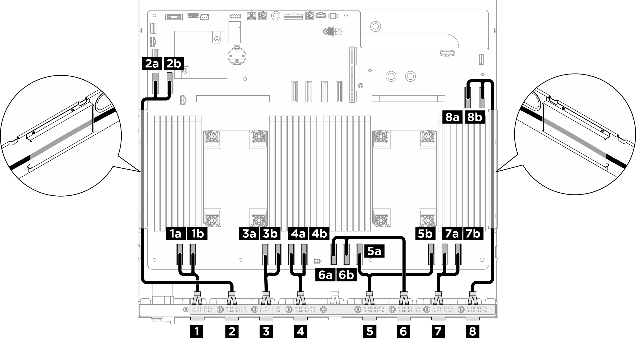
| Cable | From | To |
|---|---|---|
| 1 | Rear switch cable harness: MCIO 1 cable | 1a System board: MCIO connector 1 (MCIO1A) |
| 1b System board: MCIO connector 1 (MCIO1B) | ||
| 2 | Rear switch cable harness: MCIO 9 cable | 2a System board: MCIO connector 9 (MCIO9A) |
| 2b System board: MCIO connector 9 (MCIO9B) | ||
| 3 | Rear switch cable harness: MCIO 2 cable Note
| 3a System board: MCIO connector 2 (MCIO2B) |
| 3b System board: MCIO connector 2 (MCIO2A) | ||
| 4 | Rear switch cable harness: MCIO 3 cable | 4a System board: MCIO connector 3 (MCIO3A) |
| 4b System board: MCIO connector 3 (MCIO3B) | ||
| 5 | Rear switch cable harness: MCIO 5 cable Note
| 5a System board: MCIO connector 5 (MCIO5B) |
| 5b System board: MCIO connector 5 (MCIO5A) | ||
| 6 | Rear switch cable harness: MCIO 10 cable | 6a System board: MCIO connector 10 (MCIO10A) |
| 6b System board: MCIO connector 10 (MCIO10B) | ||
| 7 | Rear switch cable harness: MCIO 6 cable | 7a System board: MCIO connector 6 (MCIO6A) |
| 7b System board: MCIO connector 6 (MCIO6B) | ||
| 8 | Rear switch cable harness: MCIO 7 cable Note
| 8a System board: MCIO connector 7 (MCIO7B) |
| 8b System board: MCIO connector 7 (MCIO7A) |
In 8U GPU shuttle
Signal cables
Figure 2. PCIe switch board cable routing
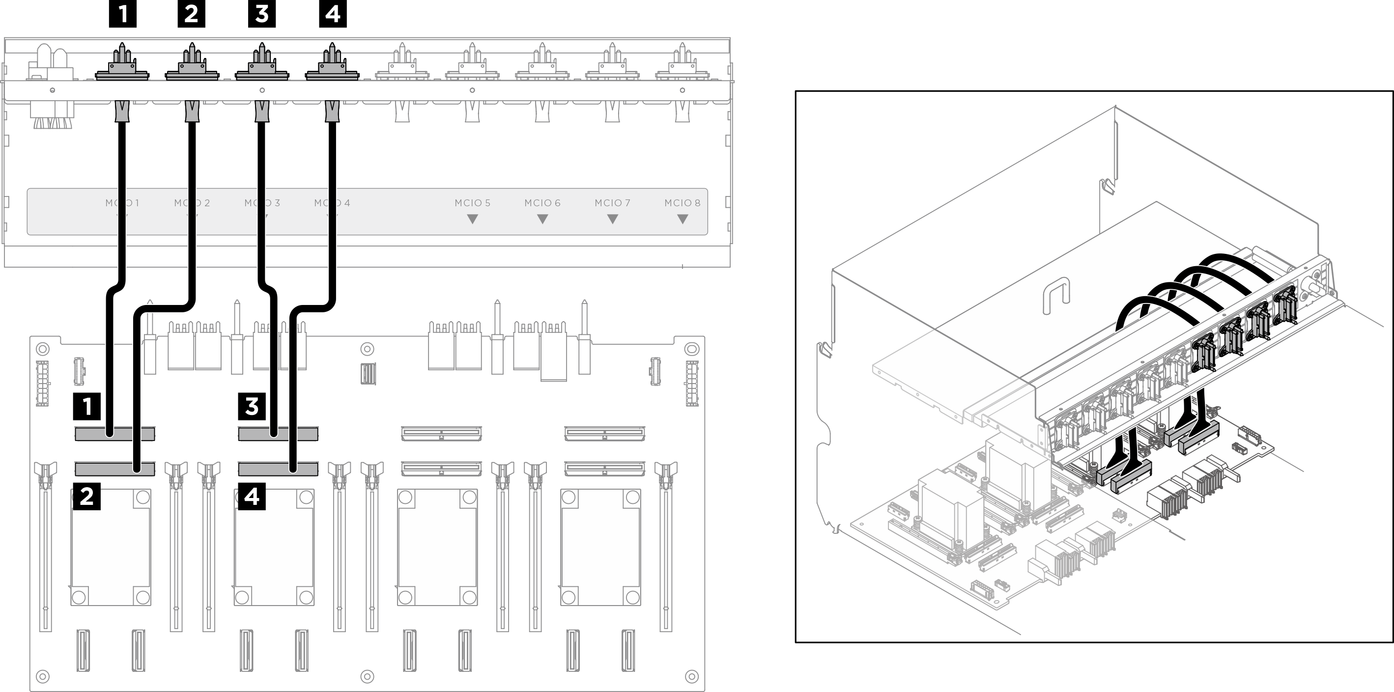
| Cable | From | To | Label |
|---|---|---|---|
| 1 | Front PCIe switch cable harness: MCIO 1 cable | PCIe switch board: MCIO connector 1 (MCIO1) | MCIO 1 |
| 2 | Front PCIe switch cable harness: MCIO 2 cable | PCIe switch board: MCIO connector 2 (MCIO2) | MCIO 2 |
| 3 | Front PCIe switch cable harness: MCIO 3 cable | PCIe switch board: MCIO connector 3 (MCIO3) | MCIO 3 |
| 4 | Front PCIe switch cable harness: MCIO 4 cable | PCIe switch board: MCIO connector 4 (MCIO4) | MCIO 4 |
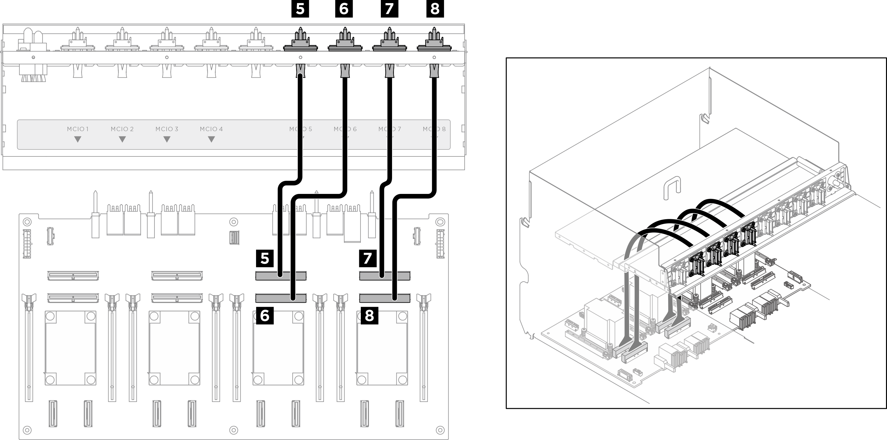
| 5 | Front PCIe switch cable harness: MCIO 5 cable | PCIe switch board: MCIO connector 5 (MCIO5) | MCIO 5 |
| 6 | Front PCIe switch cable harness: MCIO 6 cable | PCIe switch board: MCIO connector 6 (MCIO6) | MCIO 6 |
| 7 | Front PCIe switch cable harness: MCIO 7 cable | PCIe switch board: MCIO connector 7 (MCIO7) | MCIO 7 |
| 8 | Front PCIe switch cable harness: MCIO 8 cable | PCIe switch board: MCIO connector 8 (MCIO8) | MCIO 8 |
Divide the cables connected to the PCIe switch board into four bundles, and secure them with cable ties.
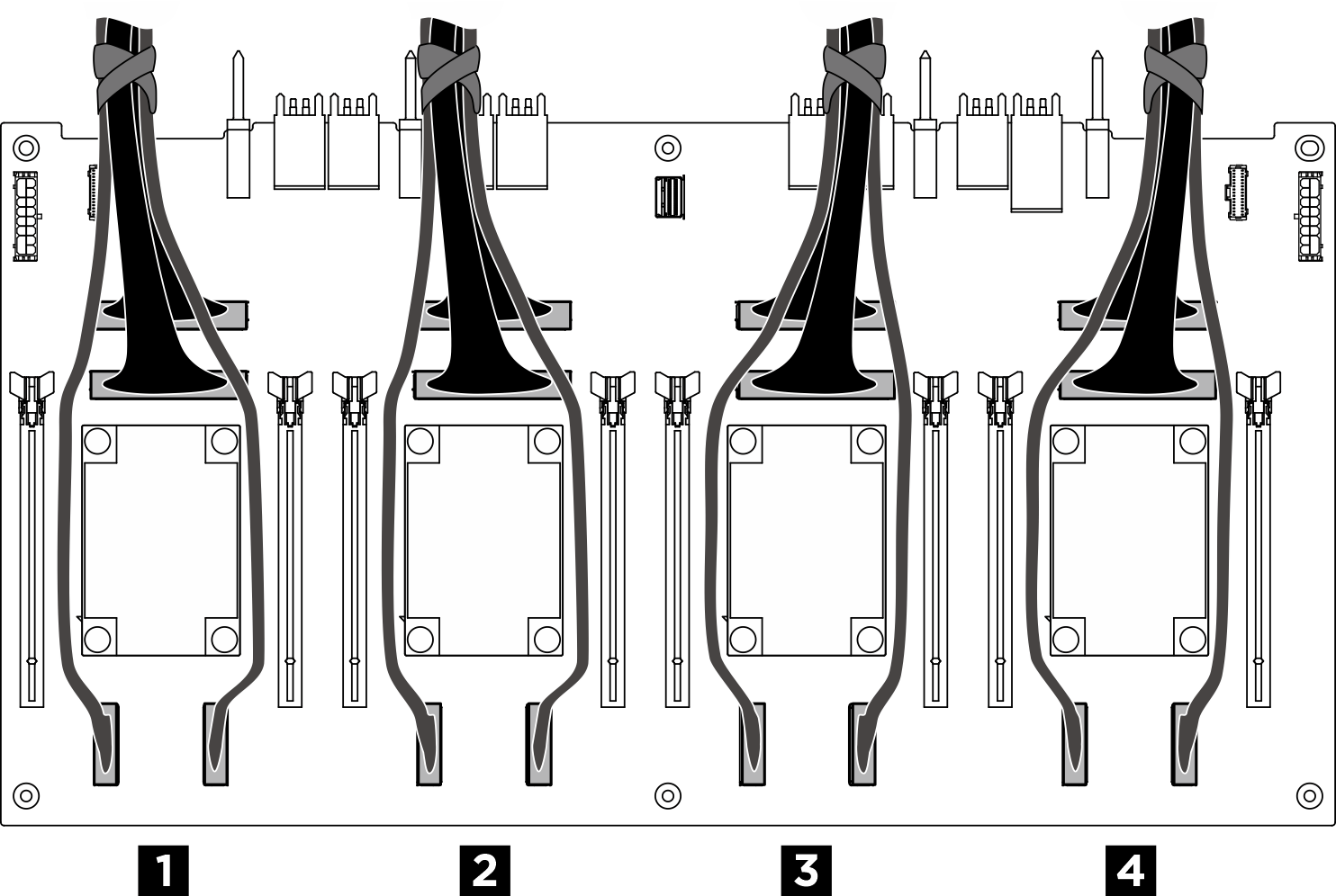
Figure 3. Securing cables with cable ties
| Bundle | Cable |
| 1 |
|
| 2 |
|
| 3 |
|
| 4 |
|
GPU management cable
Figure 4. PCIe switch board cable routing (GPU management cable)
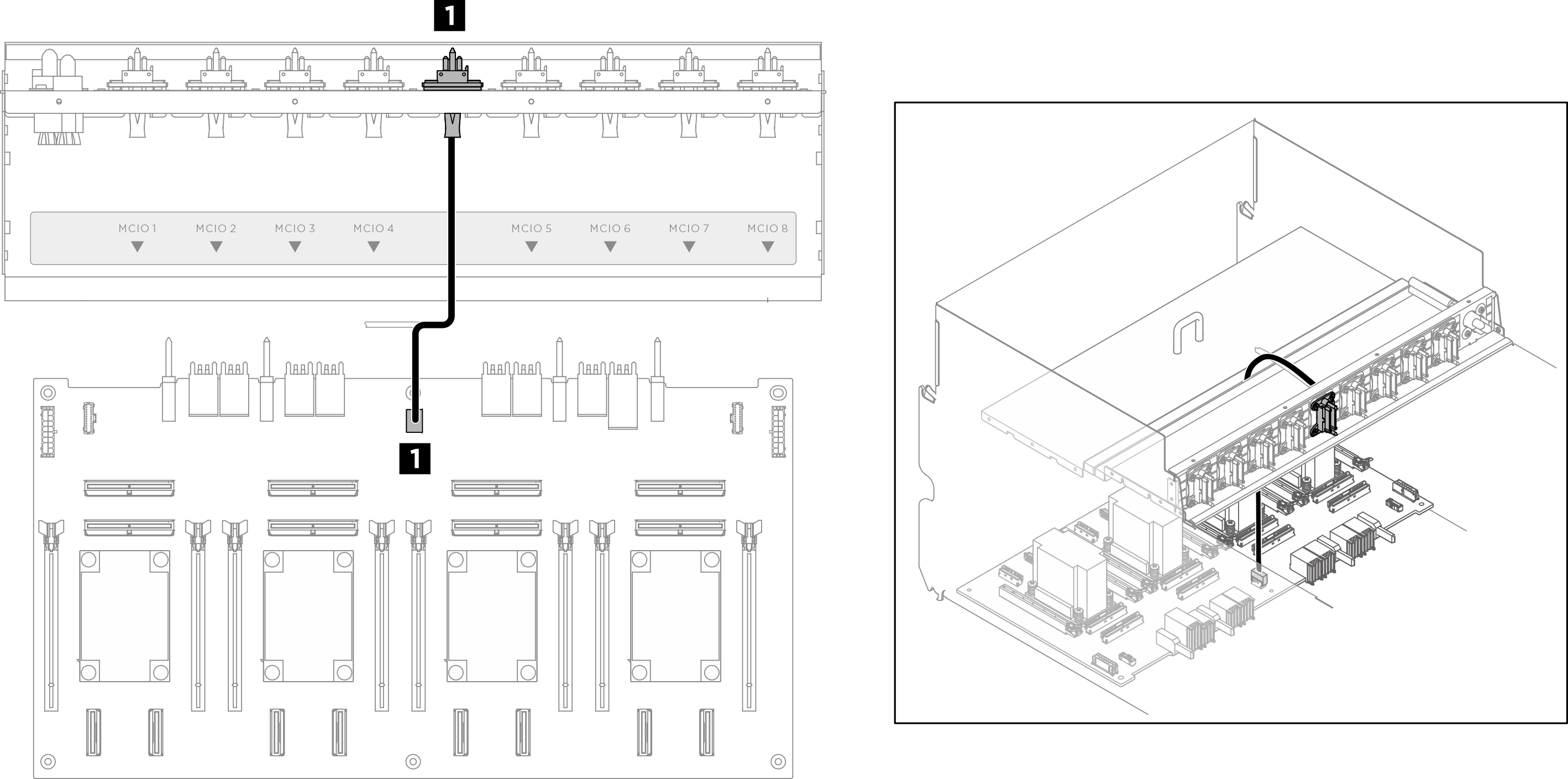
| Cable | From | To |
|---|---|---|
| 1 | Front PCIe switch cable harness: GPU management cable | PCIe switch board: GPU management connector (MGMT) |
For GPU management cable routing on the system board, see Front I/O module and integrated diagnostics panel cable routing.
Power and sideband cables
Note
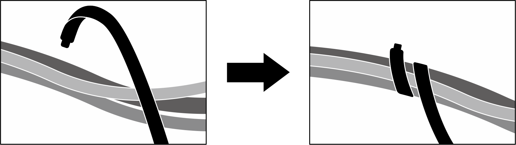
Make sure to route the cables through the cable clips as instructed.
Figure 5. PCIe switch board cable routing (power and sideband cables)
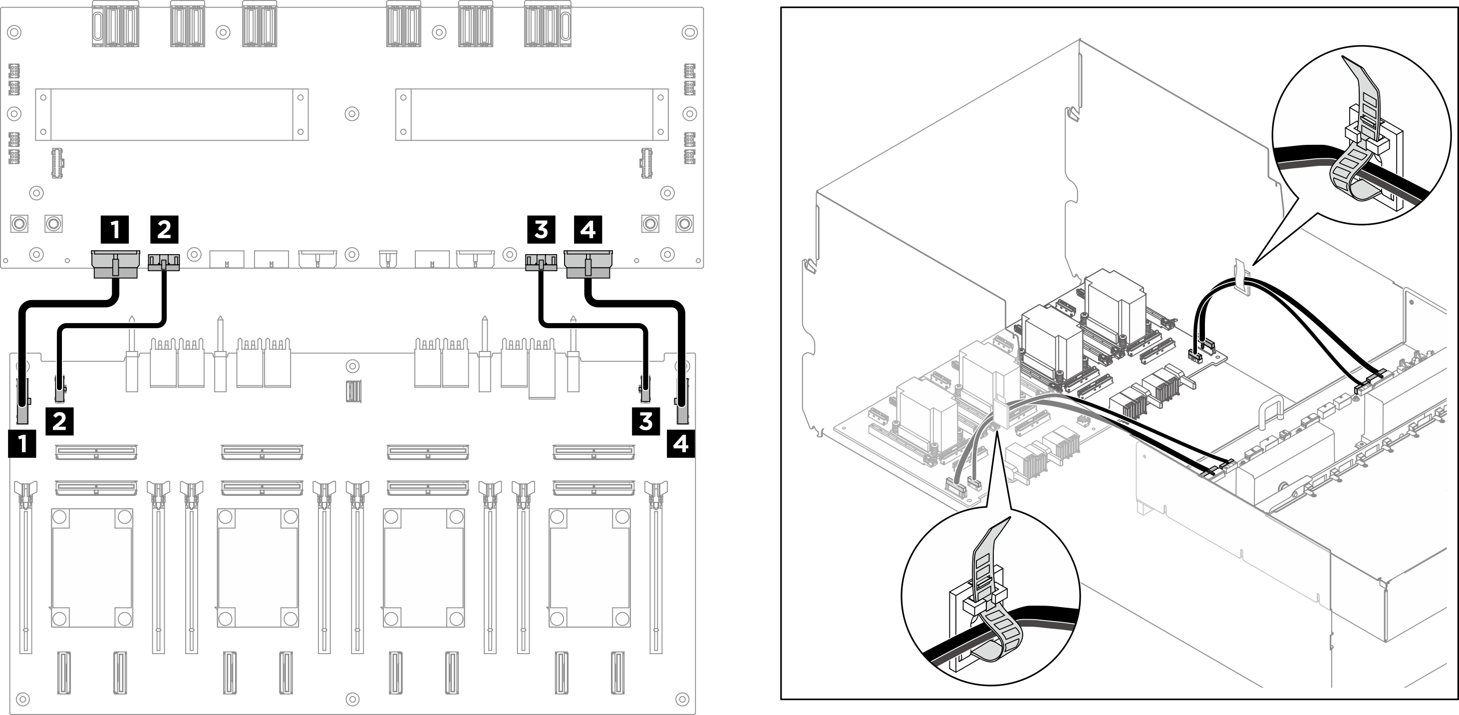
| Cable | From | To |
|---|---|---|
| 1 | PCIe switch board: Power distribution board power connector 1 (PDB PWR1) | Power distribution board: PCIe switch board power connector 1 (FRONT RISER PWR1) |
| 2 | PCIe switch board: Power distribution board sideband connector 1 (PDB SB1) | Power distribution board: PCIe switch board sideband connector 1 (SWSB1) |
| 3 | PCIe switch board: Power distribution board sideband connector 2 (PDB SB2) | Power distribution board: PCIe switch board sideband connector 2 (SWSB2) |
| 4 | PCIe switch board: Power distribution board power connector 2 (PDB PWR2) | Power distribution board: PCIe switch board power connector 2 (FRONT RISER PWR2) |
Give documentation feedback