PCIe riser cable routing
Use the section to understand the cable routing for the PCIe risers.
Note
- Connections between connectors; 1↔1, 2↔2, 3↔3, ... n↔n
- When routing the cables, ensure that all cables are routed appropriately through the cable guides.
- A label on each cable indicates the connection source and destination. This information is in the format RY-X and P Z. Where Y indicates the PCIe riser number, X indicates the connector on the riser card, and Z indicates the connector on the system board.
PCIe riser cable routing
Figure 1. PCIe riser cable routing
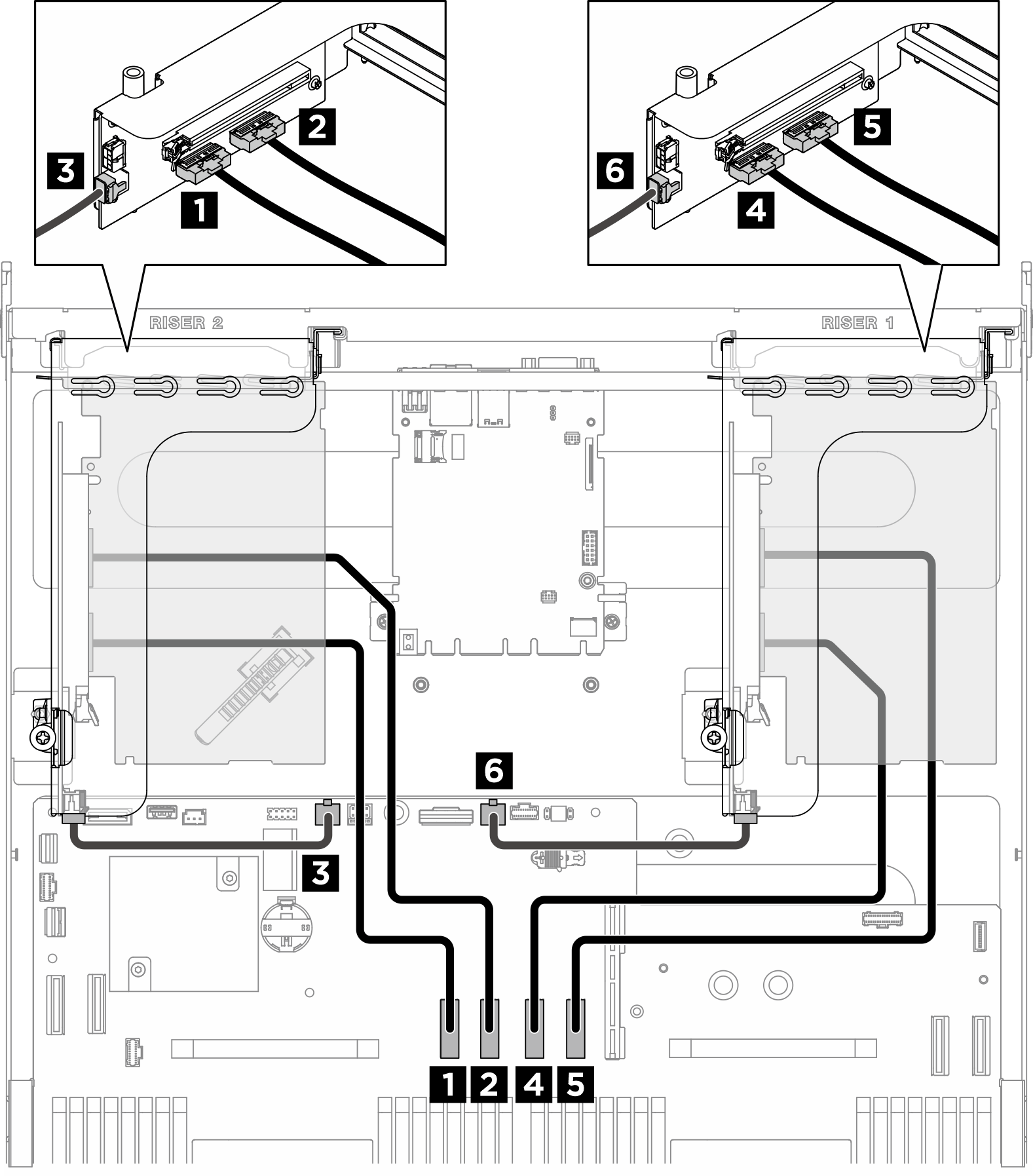
| From | To | Label |
|---|---|---|
| 1 PCIe riser 2 signal connector (MCIO 1) | System board: PCIe Riser 2 signal connectors (MCIO4B) |
|
| 2 PCIe riser 2 signal connector (MCIO 2) | System board: PCIe Riser 2 signal connectors (MCIO4A) |
|
| 3 PCIe Riser 2 power connector (RISER PWR) | System board: PCIe Riser 2 power and sideband connector (BP PWR/SIG 2) |
|
| 4 PCIe riser 1 signal connector (MCIO 1) | System board: PCIe Riser 1 signal connectors (MCIO8A) |
|
| 5 PCIe riser 1 signal connector (MCIO 2) | System board: PCIe Riser 1 signal connectors (MCIO8B) |
|
| 6 PCIe Riser 1 power connector (RISER PWR) | System board: PCIe Riser 1 power and sideband connector (BP PWR/SIG 3) |
|
DPU adapter power cable routing
| DPU adapter on PCIe riser 2 | DPU adapter on PCIe riser 1 |
|---|---|
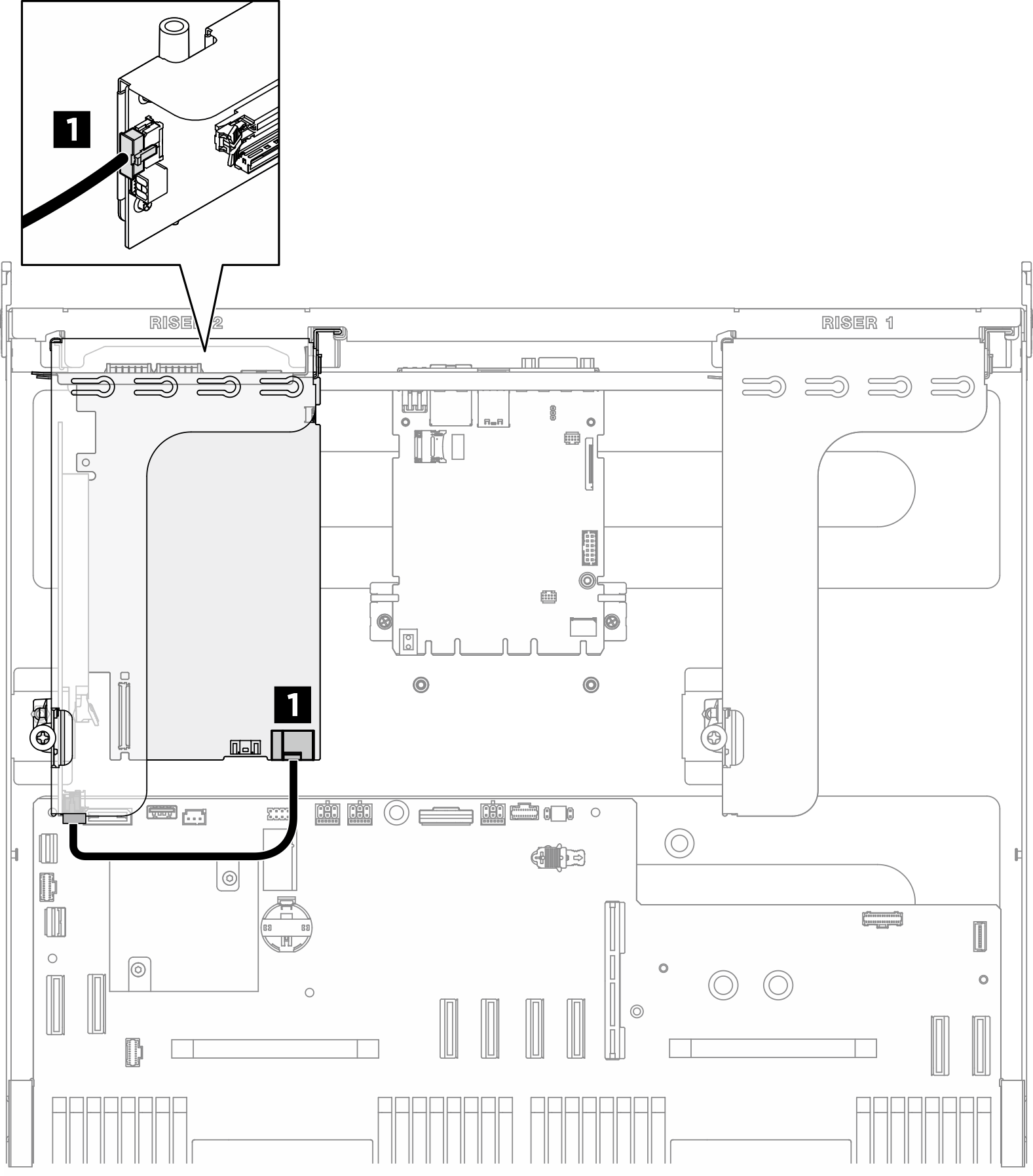 | 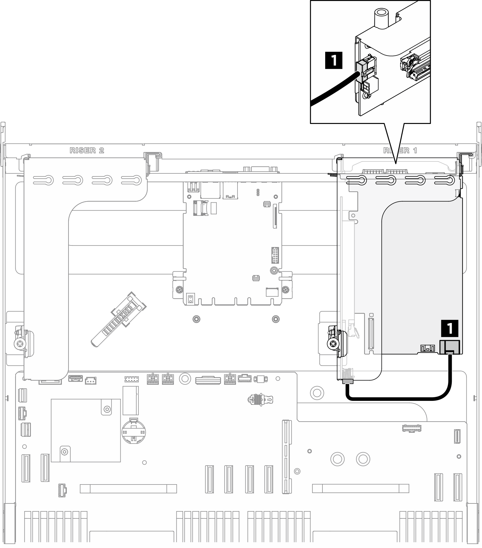 |
| Cable | From | To |
|---|---|---|
| 1 | DPU adapter: Power connector | PCIe riser 1 or 2: Power connector |
Give documentation feedback