Disassemble the system board for recycle
Follow the instructions in this section to disassemble the system board before recycling.
About this task
Before disassembling the system board:
- Remove the 2U compute shuttle. See Remove the 2U compute shuttle.
- Remove the processor air baffle. See Remove the processor air baffle.
- If applicable, remove the PCIe riser assembly(ies). See Remove a PCIe riser assembly.
- If applicable, remove the system I/O board. See Remove the system I/O board.
- Remove all the processors and the heat sinks. See Remove a processor and heat sink.
- Remove all the memory modules. See Remove a memory module.
- Remove the CMOS battery (CR2032). See Remove the CMOS battery (CR2032).
- Refer to local environmental, waste or disposal regulations to ensure compliance.
Procedure
- Remove the two cable guides.
- Unfasten the two screws that secure the cable guide to the 2U compute shuttle; then, lift the cable guide out of the 2U compute shuttle.Figure 1. Cable guide removal
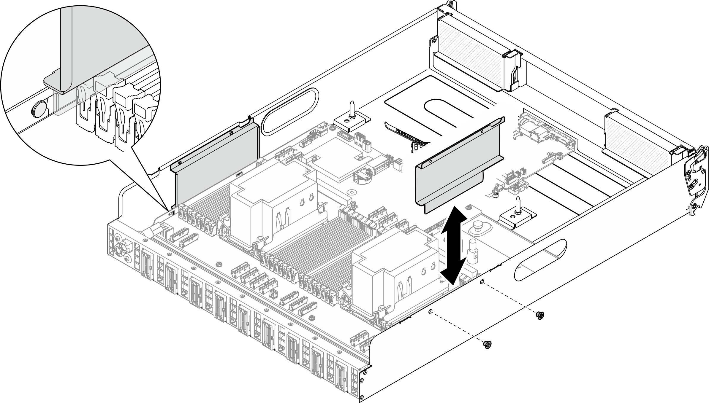
- Unfasten the two screws that secure the cable guide to the 2U compute shuttle; then, lift the cable guide out of the 2U compute shuttle.
- Disengage the system board.
 Loosen the (1) thumbscrew to release the system board.
 Slide the system board towards the front of the 2U compute shuttle as illustrated to disengage it from the shuttle.Figure 2. System board disengagement
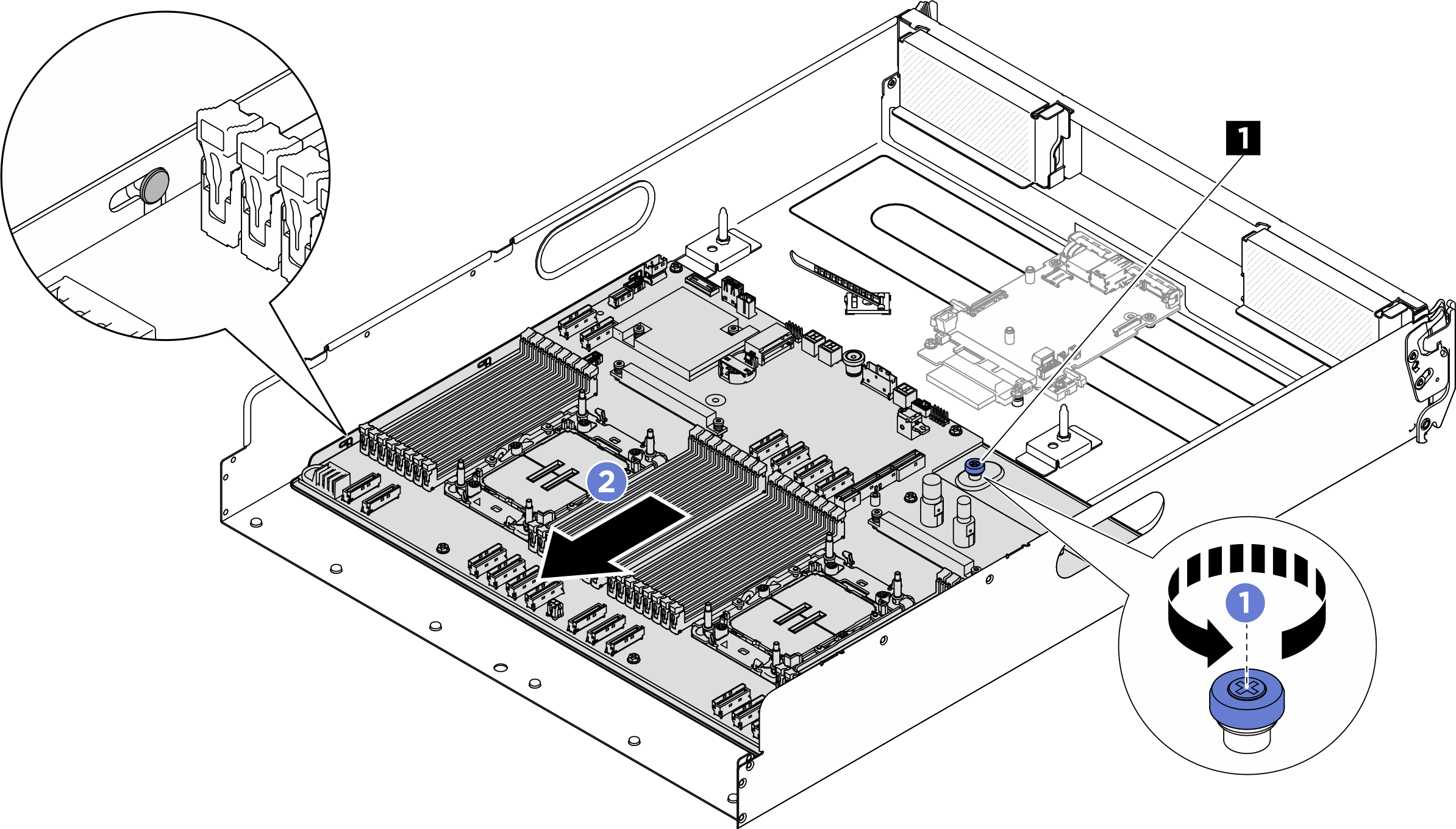
1 Thumbscrew
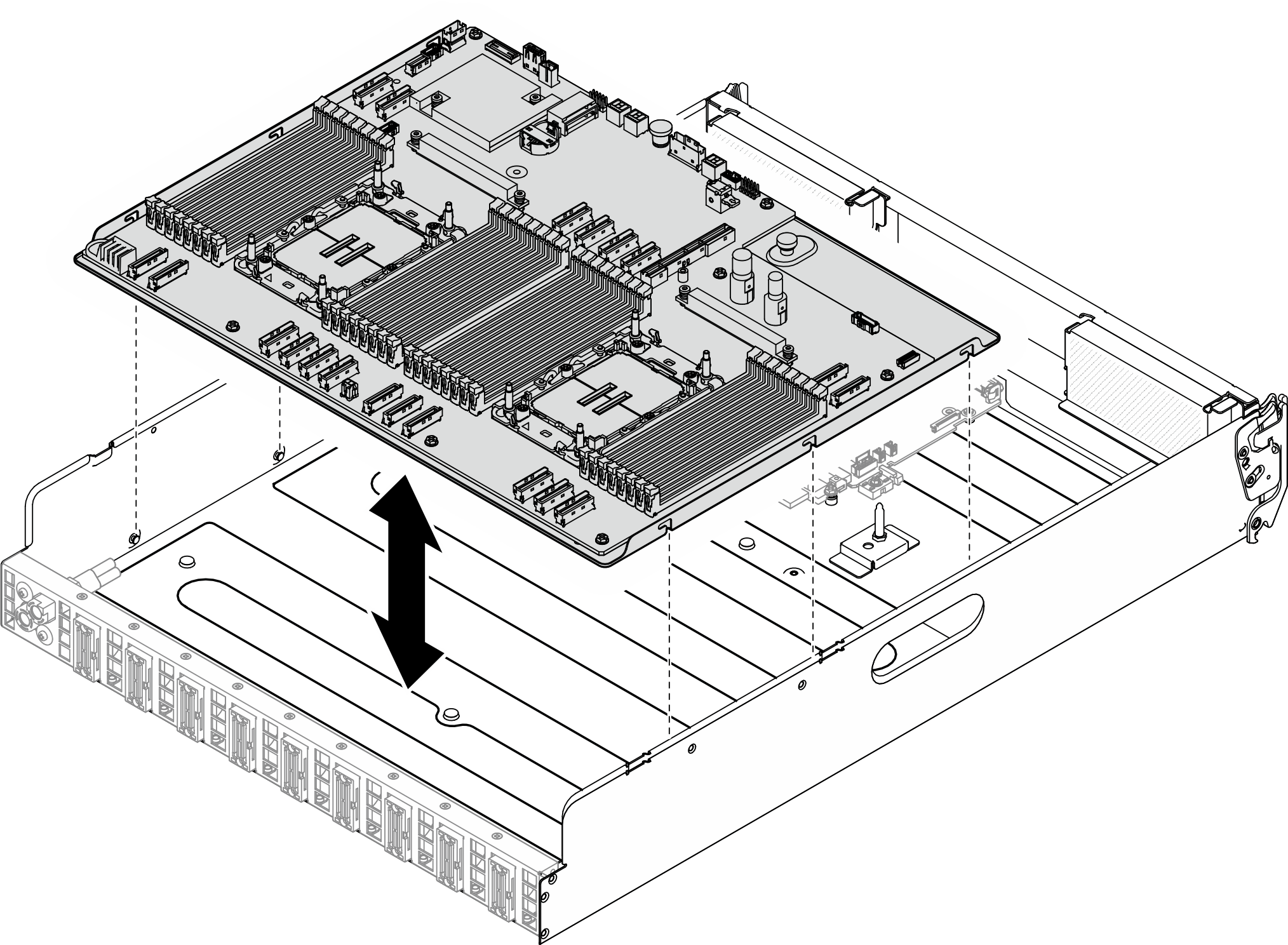
- Remove the system board from the 2U compute shuttle.Figure 3. System board removal
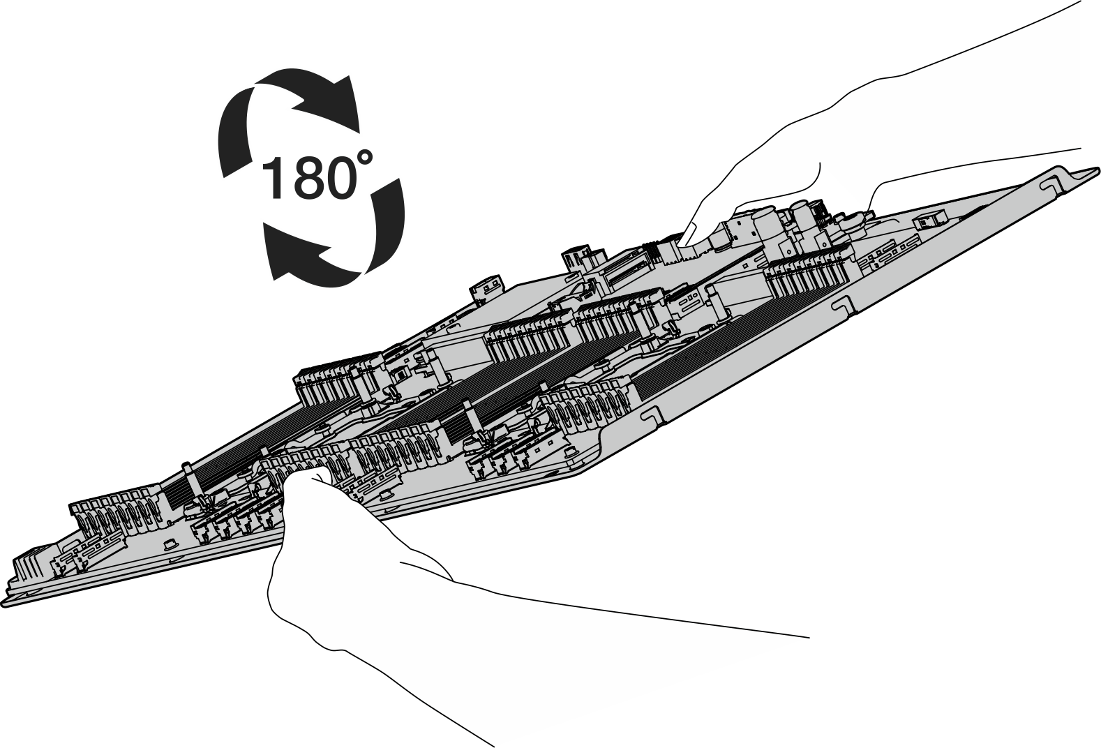
- Separate the system board from the supporting sheet metal.
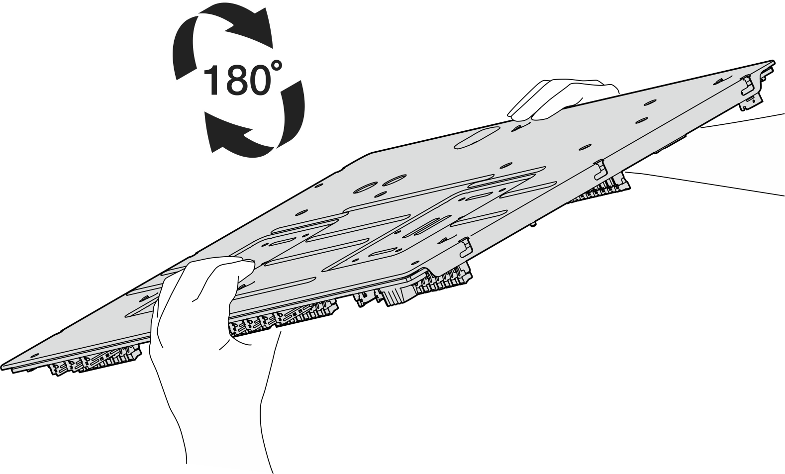
- Carefully turn the system board upside down.Figure 4. Turning the system board upside down
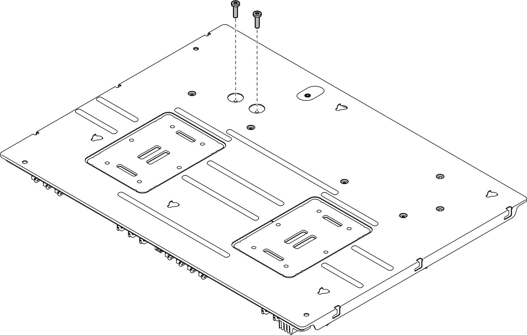
- Unfasten the two screws from the bottom of the supporting sheet metal to remove the power connectors.Figure 5. Screw removal
- Carefully turn the system board right-side up.Figure 6. Turning the system board right-side up
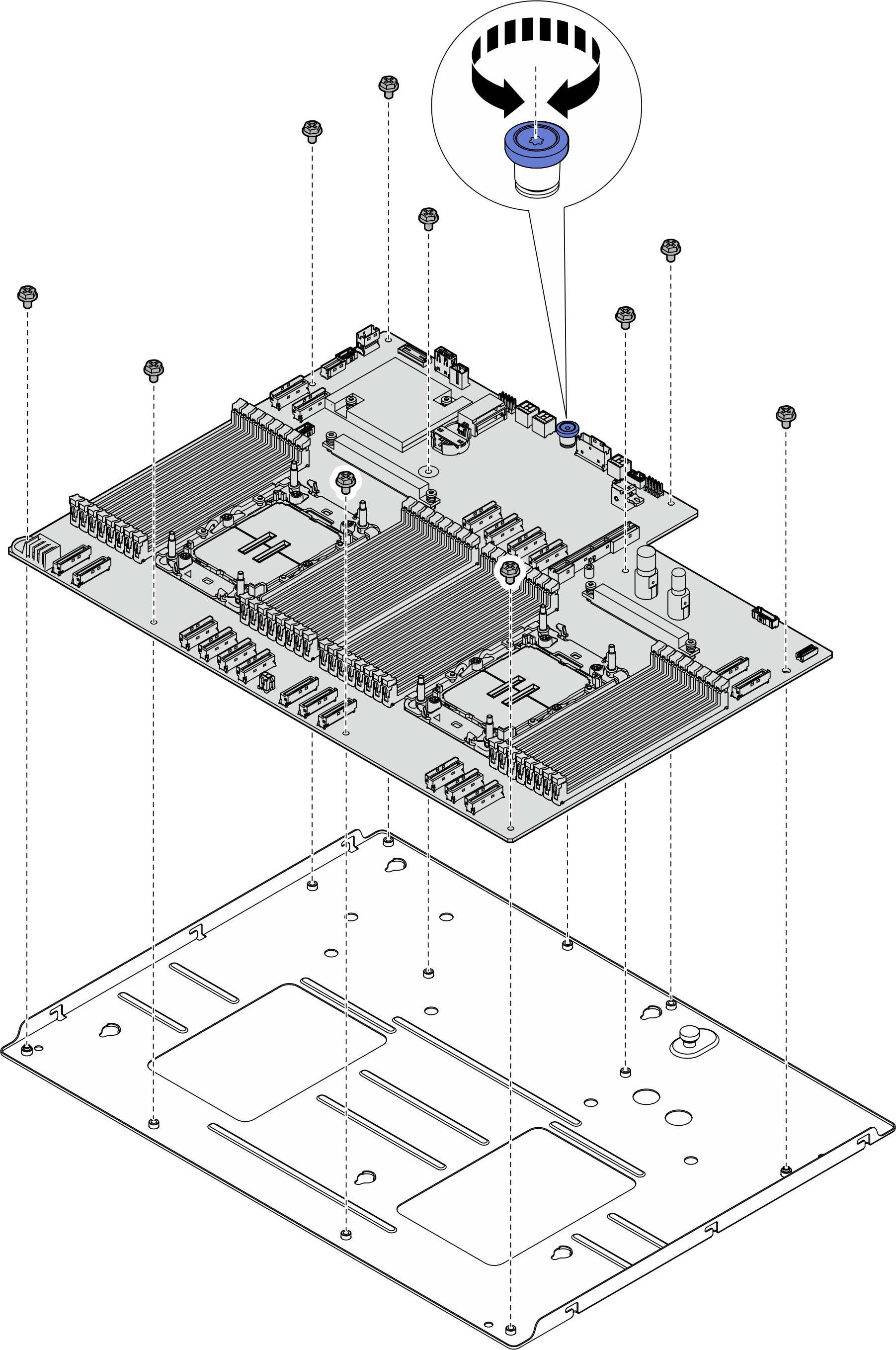
- Remove the thumbscrew and ten screws from the system board as illustrated:Figure 7. Component removal
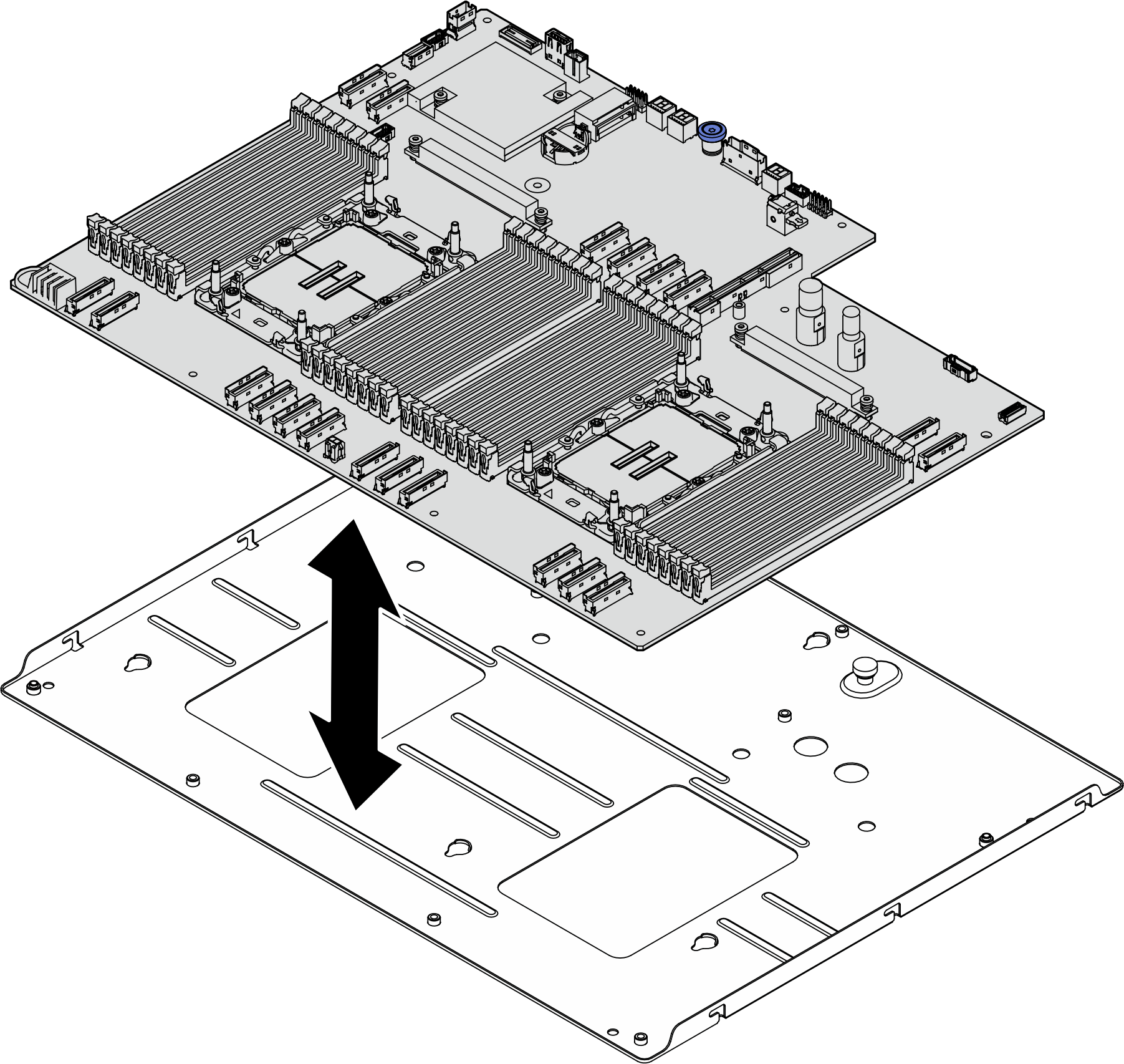
- Separate the system board from the supporting sheet metal.Figure 8. System board disassembly
- Carefully turn the system board upside down.
After you finish
After disassembling the system board, recycle the unit in compliance with local regulations.
Give documentation feedback