Front view of the sever model with 2.5-inch drives
This section contains information on the front view of the sever model with 2.5-inch drives.
Front view of the sever model with 2.5-inch drives
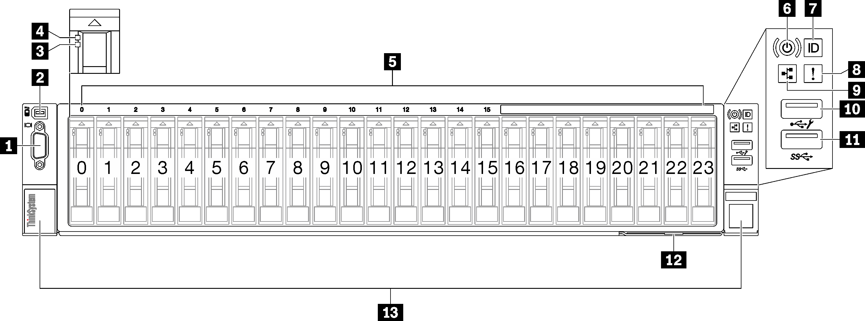
| 1 VGA connector | 8 System error LED (yellow) |
| 2 External diagnostics connector | 9 Network activity LED (green) |
| 3 Drive status LED (yellow) | 10 USB 2.0 connector with Lenovo XClarity Controller management |
| 4 Drive activity LED (green) | 11 USB 3.1 Gen 1 (5 Gbps) connector |
| 5 2.5-inch drive bays | 12 Pull-out information tab |
| 6 Power button/LED (green) | 13 Rack release latches |
| 7 System ID button/LED (blue) |
1 VGA connector
Connect a monitor to this connector.
2 External diagnostics connector
Connect the external diagnostics handset to this connector. See External diagnostics handset for more details.
3 Drive status LED (yellow)
- The LED is lit: the drive has failed.
- The LED is flashing slowly (once per second): the drive is being rebuilt.
- The LED is flashing rapidly (three times per second): the drive is being identified.
4 Drive activity LED (green)
Each hot-swap drive comes with an activity LED. When this LED is flashing, it indicates that the drive is in use.
5 2.5-inch drive bays
Install 2.5-inch drives to these bays. See Install a 2.5-inch hot-swap drive .
6 Power button/LED (green)
| Status | Color | Description |
|---|---|---|
| Off | None | Power is not present, or the power supply has failed. |
| Fast blinking (about four flashes per second) | Green |
|
| Slow blinking (about one flash per second) | Green | The server is off and is ready to be powered on (standby state). |
| Solid on | Green | The server is on and running. |
7 System ID button/LED (blue)
Use this system ID button and the blue system ID LED to visually locate the server. Each time you press the system ID button, the state of the system ID LED changes. The LED can be changed to on, blinking, or off. You can also use the Lenovo XClarity Controller or a remote management program to change the state of the system ID LED to assist in visually locating the server among other servers.
8 System error LED (yellow)
| Status | Color | Description | Action |
|---|---|---|---|
| On | Yellow | An error has been detected on the server. Causes might include one or more of the following errors:
| Check the Event log to determine the exact cause of the error. |
| Off | None | The server is off or the server is on and is working correctly. | None. |
9 Network Activity LED (green)
| Status | Color | Description |
|---|---|---|
| On | Green | The server is connected to a network. |
| Blinking | Green | The network is connected and active. |
| Off | None | The server is disconnected from the network. |
10 USB 2.0 connector with Lenovo XClarity Controller management
Connection to Lenovo XClarity Controller is primarily intended for users with a mobile device running the Lenovo XClarity Controller mobile application. When a mobile device is connected to this USB port, an Ethernet over USB connection is established between the mobile application running on the device and the Lenovo XClarity Controller.
Select Network in BMC Configuration to view or modify settings.
Four types of settings are available:
Host only mode
In this mode, the USB port is always solely connected to the server.
BMC only mode
In this mode, the USB port is always solely connected to Lenovo XClarity Controller.
Shared mode: owned by BMC
In this mode, connection to the USB port is shared by the server and Lenovo XClarity Controller, while the port is switched to Lenovo XClarity Controller.
Shared mode: owned by host
In this mode, connection to the USB port is shared by the server and Lenovo XClarity Controller, while the port is switched to the server.
11 USB 3.1 Gen 1 (5 Gbps) connector
The USB 3.1 Gen 1 (5 Gbps) connector can be used to attach a USB-compatible device, such as a USB keyboard, USB mouse, or USB storage device.
12 Pull-out information tab
This tab contains network information such as MAC address and XCC network access label.
13 Rack release latches
Press on the latch on both sides to disengage the server from the rack and slide it out.