Rear view of the sever model with three PCIe risers
This section contains information on the rear view of the sever model with three PCIe risers.
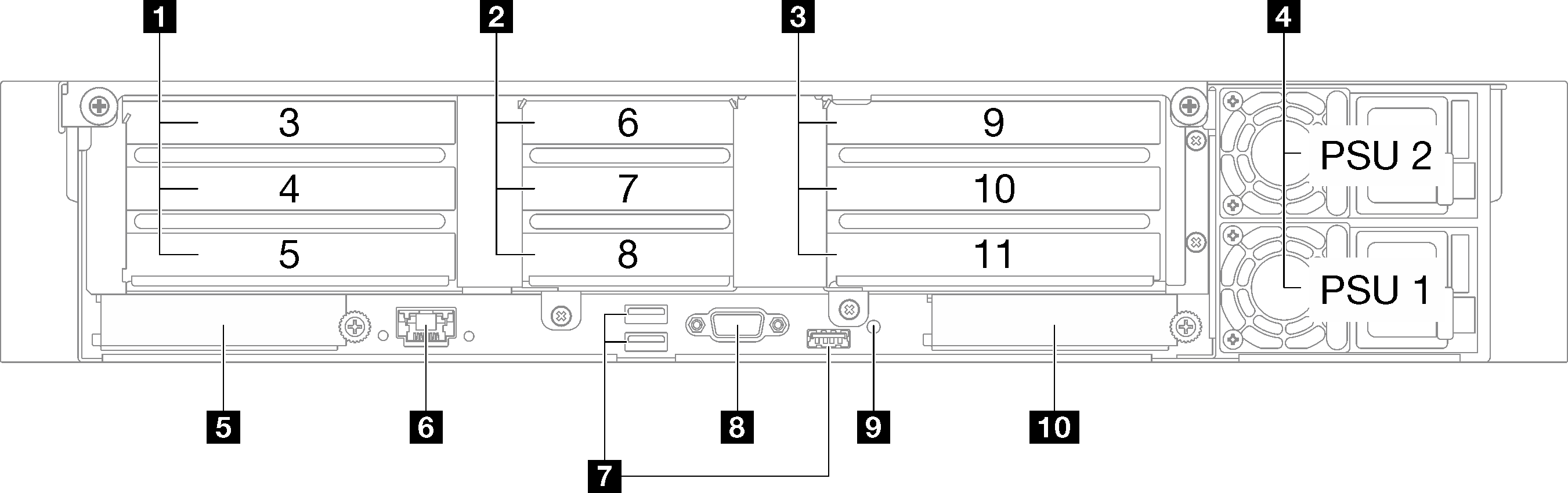
| 1 PCIe riser 1 (PCIe slot 3-5) | 6 XCC system management port (1 GB RJ-45) |
| 2 PCIe riser 2 (PCIe slot 6-8) | 7 USB 3.1 Gen 1 (5 Gbps) connectors (total of three connectors) |
| 3 PCIe riser 3 (PCIe slot 9-11) | 8 VGA connector |
| 4 Power supply units | 9 NMI button |
| 5 OCP slot 1 (PCIe slot 1) | 10 OCP slot 2 (PCIe slot 2) |
1 PCIe riser 1 (PCIe slot 3-5)
| PCIe slot | x8/x16/x16 PCIe G4 Riser 1/3 FHFL | 7mm/x16 PCIe G4 Riser 1 FHHL | x16/x16 PCIe G5 Riser 1/3 FHFL | 7mm/x16 PCIe G5 Riser 1 FHHL |
|---|---|---|---|---|
| 3 | x16 (Gen4 x8) | 7mm drive cage | N/A | 7mm drive cage |
| 4 | x16 (Gen4 x16) * | x16 (Gen5 x16) * | ||
| 5 | x16 (Gen4 x16) | x16 (Gen4 x16) | x16 (Gen5 x16) | x16 (Gen5 x16) |
2 PCIe riser 2 (PCIe slot 6-8)
| PCIe slot | x16/x8/x8 PCIe G4 Riser 2/A/B/C HHHL | x16/x8/Serial PCIe G4 Riser 2/C HHHL | x16/x8/x8 PCIe G5 Riser 2/A/B/C HHHL | x16/x8/Serial PCIe G5 Riser 2/C HHHL |
|---|---|---|---|---|
| 6 | x16 (Gen4 x16) | x16 (Gen4 x16) | x16 (Gen5 x16) | x16 (Gen5 x16) |
| 7 | x16 (Gen4 x8) | x16 (Gen4 x8) | x16 (Gen5 x8) | x16 (Gen5 x8) |
| 8 | x16 (Gen4 x8) | Serial port bay | x16 (Gen4 x8) | Serial port bay |
3 PCIe riser 3 (PCIe slot 9-11)
| PCIe slot | x8/x16/x16 PCIe G4 Riser 1/3 FHFL | x16/x16 PCIe G5 Riser 1/3 FHFL |
|---|---|---|
| 9 | x16 (Gen4 x8) | N/A |
| 10 | x16 (Gen4 x16) * | x16 (Gen5 x16) * |
| 11 | x16 (Gen4 x16) | x16 (Gen5 x16) |
4 Power supply units
Install power supply units to these bays, connect them to power cords. Make sure the power cords are connected properly. Following are the power supplies supported by this system:
- CFFv4
- 1100-watt Platinum, input power 115 Vac / 230 Vdc / 240 Vdc
- 1100-watt Titanium, input power 115 Vac / 230 Vdc/ 240 Vdc
- 1800-watt Platinum, input power 230 Vac / 240 Vdc
- 1800-watt Titanium, input power 230 Vac / 240 Vdc
- 2400-watt Platinum, input power 230 Vac / 240 Vdc
- 2600-watt Titanium, input power 230 Vac / 240 Vdc
- CRPS (Chinese Mainland Only)
- 1300-watt Platinum, input power 115 Vac / 230 Vac / 240 Vdc
- 2700-watt Platinum, input power 230 Vac / 240 Vdc
- 1600-watt, input power 336 Vdc
- 1600-watt, input power -48 Vdc
5 OCP slot 1
- The system may support a 2-port or a 4-port OCP module for network connections. Port numbering are shown in the illustrations below.Figure 2. Port numbering — 2-port OCP module
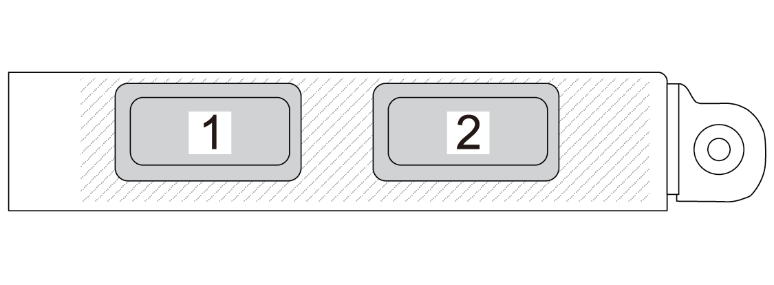 Figure 3. Port numbering — 4-port OCP 3.0 module
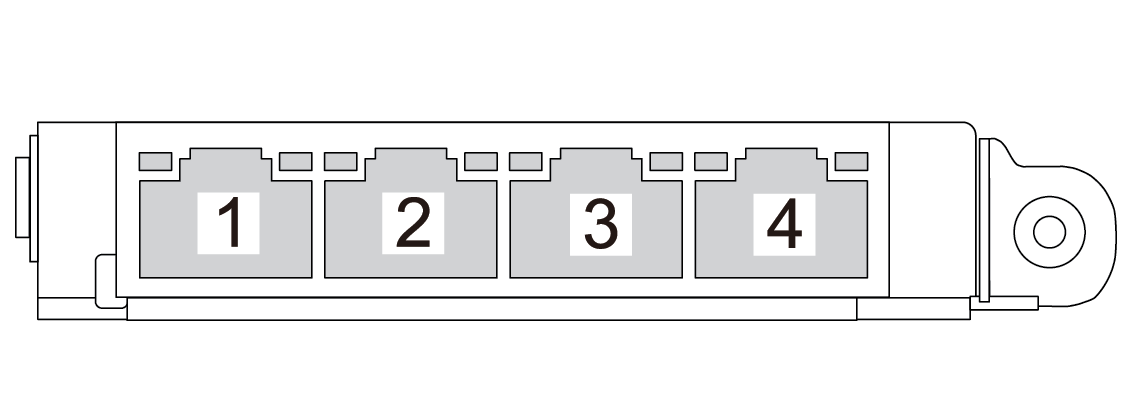
- The system may support a management NIC adapter. Install the management NIC adapter into the OCP slot in place of the OCP module to function as a redundant XCC system management port.
6 XCC system management port (1 GB RJ-45)
The server has a 1 GB RJ-45 connector dedicated to Lenovo XClarity Controller (XCC) functions. Through the system management port, you can access the Lenovo XClarity Controller directly by connecting your laptop to the management port using an Ethernet cable. Make sure that you modify the IP settings on the laptop so that it is on the same network as the server default settings. A dedicated management network provides additional security by physically separating the management network traffic from the production network.
7 USB 3.1 Gen 1 (5 Gbps) connectors
The USB 3.1 Gen 1 (5 Gbps) connectors are direct connect interfaces (DCIs) for debugging, which can be used to attach a USB-compatible device, such as a USB keyboard, USB mouse, or USB storage device.
8 VGA connector
Connect a monitor to this connector.
10 OCP slot 2