Rear view of the server model with three PCIe risers
This section contains information on the rear view of the server model with three PCIe risers.
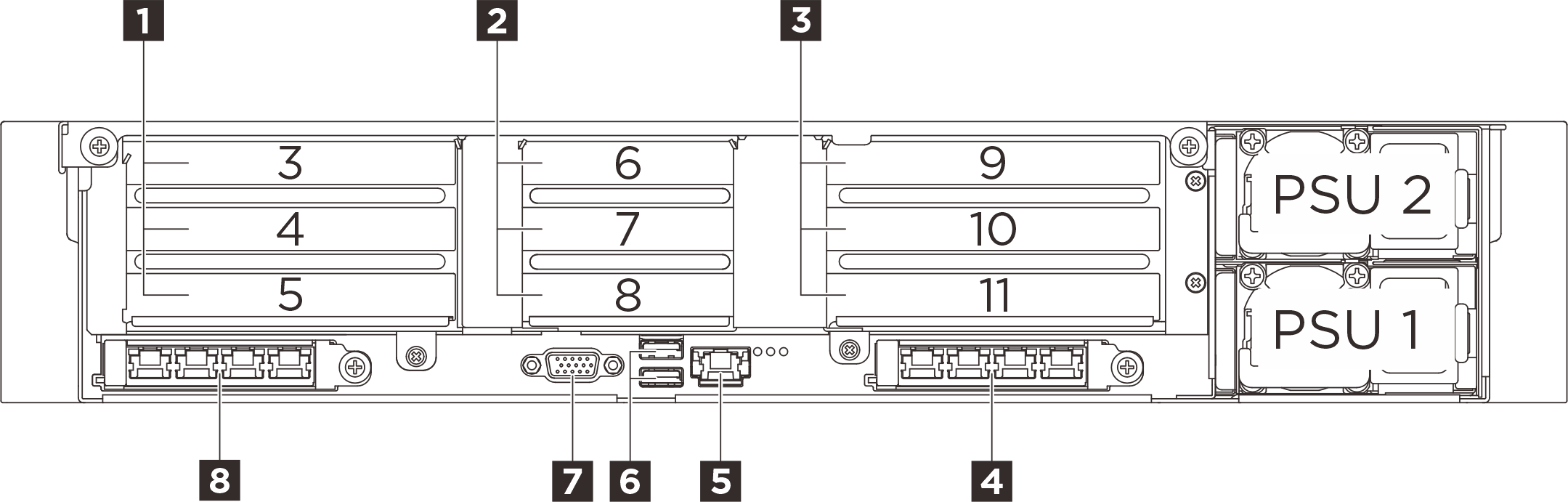
| 1 PCIe riser 1 (PCIe slot 3-5) | 2 PCIe riser 2 (PCIe slot 6-8) |
| 3 PCIe riser 3 (PCIe slot 9-11) | 4 OCP slot 2 (PCIe slot 2) |
| 5 XCC system management port (10/100/1000 Mbps RJ-45) (1 GB RJ-45) | 6 USB 3.2 Gen 1 (5 Gbps) connectors |
| 7 VGA connector | 8 OCP slot 1 (PCIe slot 1) |
1 PCIe riser 1 (PCIe slot 3-5)
| PCIe slot | Three-slot riser (with power connector) | Two-slot riser | ||
|---|---|---|---|---|
| 3 | x16 (Gen5 x8) | N/A | N/A | Rear M.2 drive bays |
| 4 | x16 (Gen5 x16) * | x16 (Gen5 x16) * | x16 (Gen5 x8) | |
| 5 | x16 (Gen4 x16) | x16 (Gen5 x16) | x16 (Gen5 x8) | x16 (Gen5 x16) |
2 PCIe riser 2 (PCIe slot 6-8)
| PCIe slot | Three-slot riser (without power connector) | |
|---|---|---|
| 6 | x16 (Gen5 x16) | x16 (Gen5 x16) |
| 7 | x16 (Gen5 x8) | x16 (Gen5 x8) |
| 8 | x16 (Gen5 x8) | Serial port bay |
3 PCIe riser 3 (PCIe slot 9-11)
| PCIe slot | Three-slot riser (with power connector) | Two-slot riser | |
|---|---|---|---|
| 9 | x16 (Gen5 x8) | N/A | N/A |
| 10 | x16 (Gen5 x16) * | x16 (Gen5 x16) * | x16 (Gen5 x8) |
| 11 | x16 (Gen4 x16) | x16 (Gen5 x16) | x16 (Gen5 x8) |
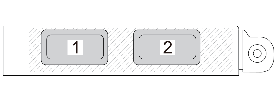
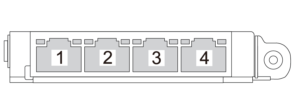
4 OCP slot 2 / 8 OCP slot 1
5 XCC system management port (10/100/1000 Mbps RJ-45) (1 GB RJ-45)
The server has a 1 GB RJ-45 connector dedicated to Lenovo XClarity Controller (XCC) functions. Through the system management port, you can access the Lenovo XClarity Controller directly by connecting your laptop to the management port using an Ethernet cable. Make sure that you modify the IP settings on the laptop so that it is on the same network as the server default settings. A dedicated management network provides additional security by physically separating the management network traffic from the production network.
6 USB 3.2 Gen 1 (5 Gbps) connectors
Top connector: The connector can be used to attach a USB-compatible device, such as a USB keyboard, USB mouse, or USB storage device.
Bottom connector: The connector can function as a regular USB 3.2 Gen 1 connector to the host OS; it can be used to attach a USB-compatible device, such as a USB keyboard, USB mouse, or USB storage device.
When there are no USB connectors at the front, this connector can function as a USB 2.0 Lenovo XClarity Controller management port.
7 VGA connector
Connect a monitor to this connector.