Remove the processor and memory expansion tray
Use this procedure to remove the processor and memory expansion tray.
Before removing the processor and memory expansion tray:
Read the safety information and installation guidelines (see Safety and Installation Guidelines).
Turn off the server and peripheral devices and disconnect the power cords and all external cables (see Power off the server).
If the server is installed in a rack, slide the server out on its rack slide rails to gain access to the top cover, or remove the server from the rack.
Remove the top cover (see Remove the top cover).
If you are replacing the processor and memory expansion tray, remove the expansion tray air baffle, DIMMs (see Remove a memory module), and PHMs (see Remove a processor and heat sink) on the expansion tray.
Figure 1. Expansion tray air baffle removal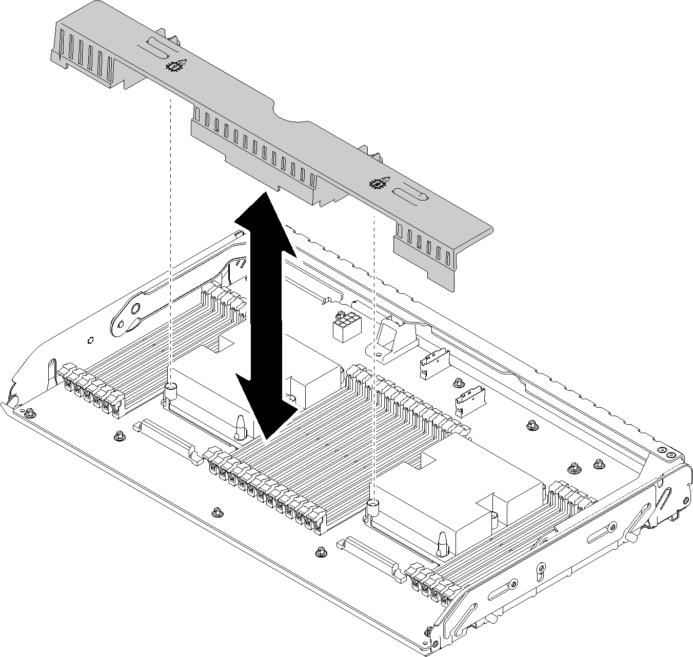 Attention
Do not remove or install DIMMs and processors on the processor and memory expansion tray when the expansion tray is removed, for the instability might cause damages to components.
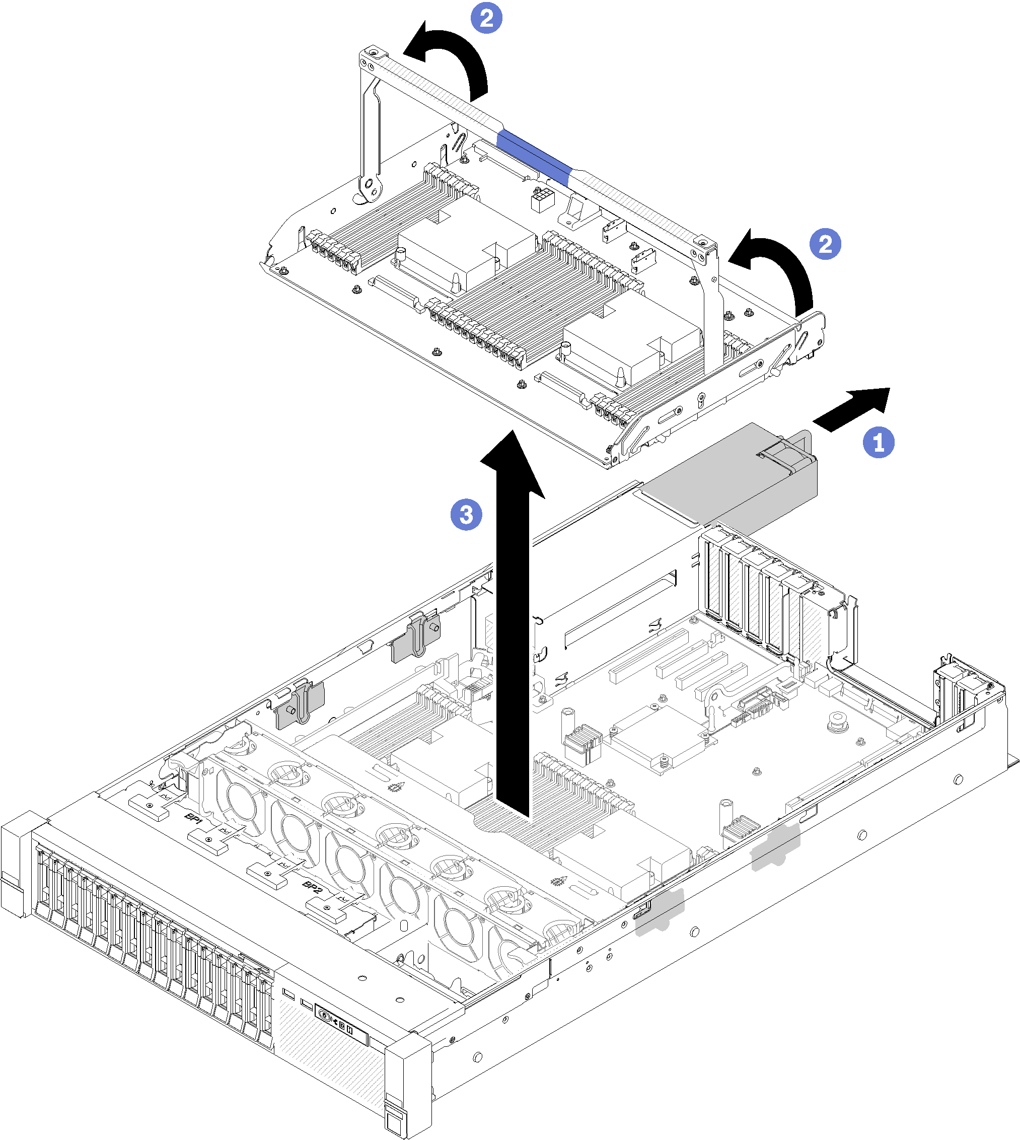
To remove the processor and memory expansion tray, complete the following steps:
- Grasp the handle of the processor and memory expansion tray; then, pull and rotate it all the way up until it is in the vertical position. This disengages the expansion tray from the system board.Figure 2. Processor and memory expansion tray removal
If you are instructed to return the component or optional device, follow all packaging instructions, and use any packaging materials for shipping that are supplied to you.
ImportantBefore you return the system board, make sure that you install the processor socket dust covers from the new system board. To replace a processor socket dust cover:Take a dust cover from the processor socket assembly on the new system board, and orient it correctly above the processor socket assembly on the removed system board.
Gently press down the dust cover legs to the processor socket assembly, pressing on the edges to avoid damage to the socket pins. You might hear a click on the dust cover is securely attached.
Make sure that the dust cover is securely attached to the processor socket assembly.
If you are planning to recycle the system board, follow the instructions in Disassemble the processor and memory expansion tray for recycle for compliance with local regulations.
Demo video