Connecting cables to the NVMe switch cards
Follow the instructions in this section to learn how to connect cables to the NVMe switch cards.
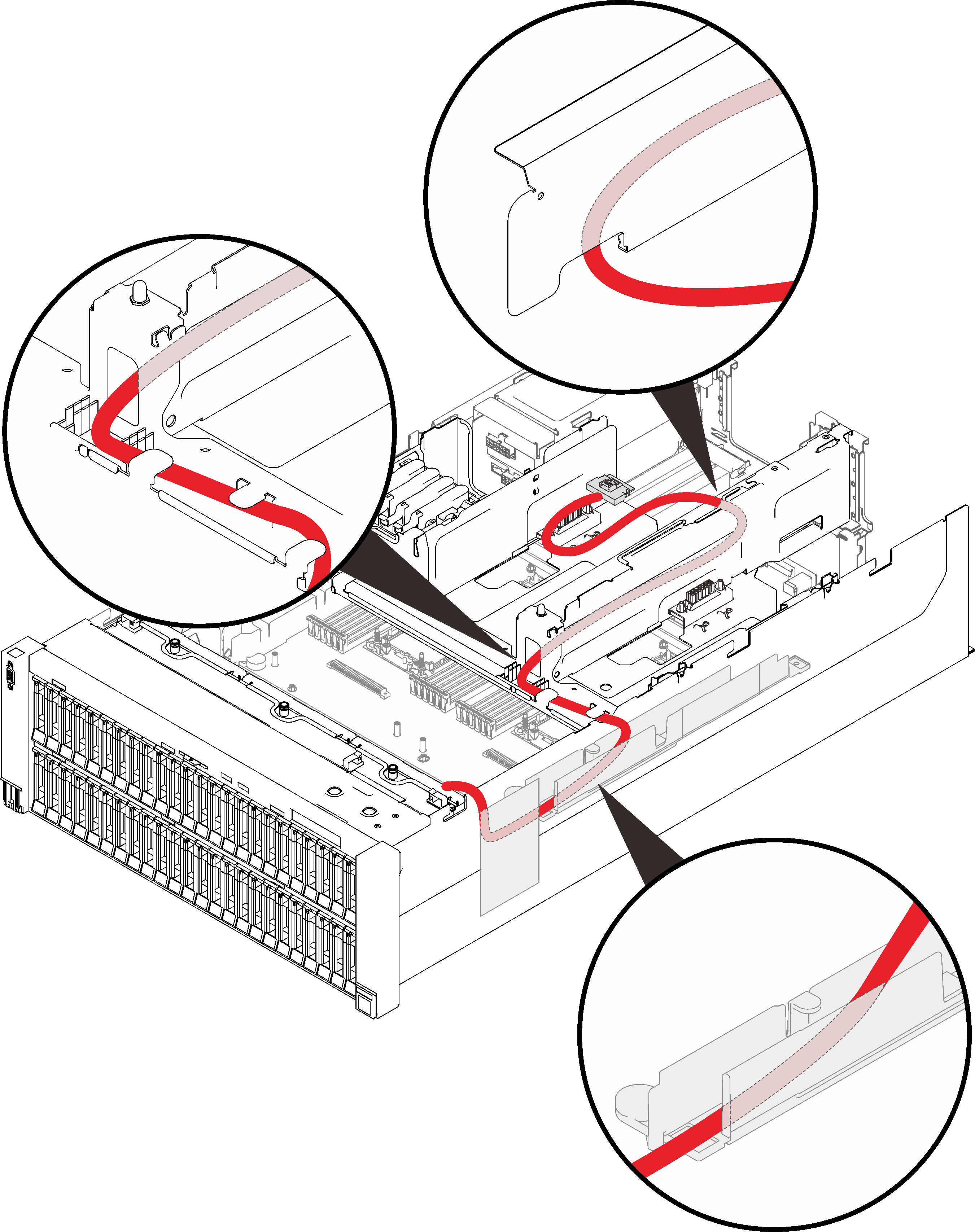
When working on cable routing plans that involve NVMe switch cards, perform the procedure in the following order.
- Rout the four PCIe cables in the following order:
- through the side cable guide in the chassis
- through the cable clips on the processor and memory expansion tray
- through the spine of the 4U PCIe expansion trayFigure 1. Routing cables for the NVMe switch cards
- Connect the four PCIe cables to the two NVMe switch cards.Figure 2. Connecting cables to the NVMe switch cards
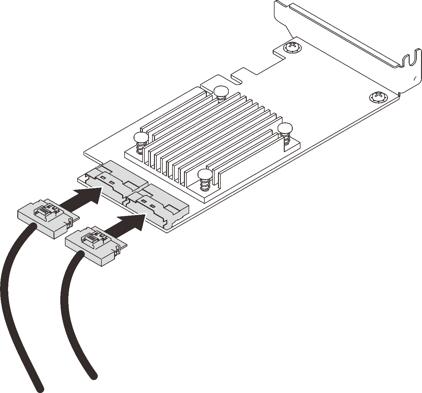 NoteMake sure to match the drive backplane and NVMe switch card connectors as following:
Table 1. Drive backplane and NVMe switch card connectors AnyBay/NVMe drive backplane connector Switch card connector 0-1 C0 2-3 C1 4-5 C0 6-7 C1 - Open the retainers of x16/x16 4U PCIe riser cage, and install the two NVMe switch cards to corresponding slots:
Table 2. NVMe switch cards and corresponding PCIe slot numbers AnyBay/NVMe drive backplane connectors PCIe slot number 1 0-1, 2-3 Slot 10 2 4-5, 6-7 Slot 12 Figure 3. Connecting cables to the NVMe switch cards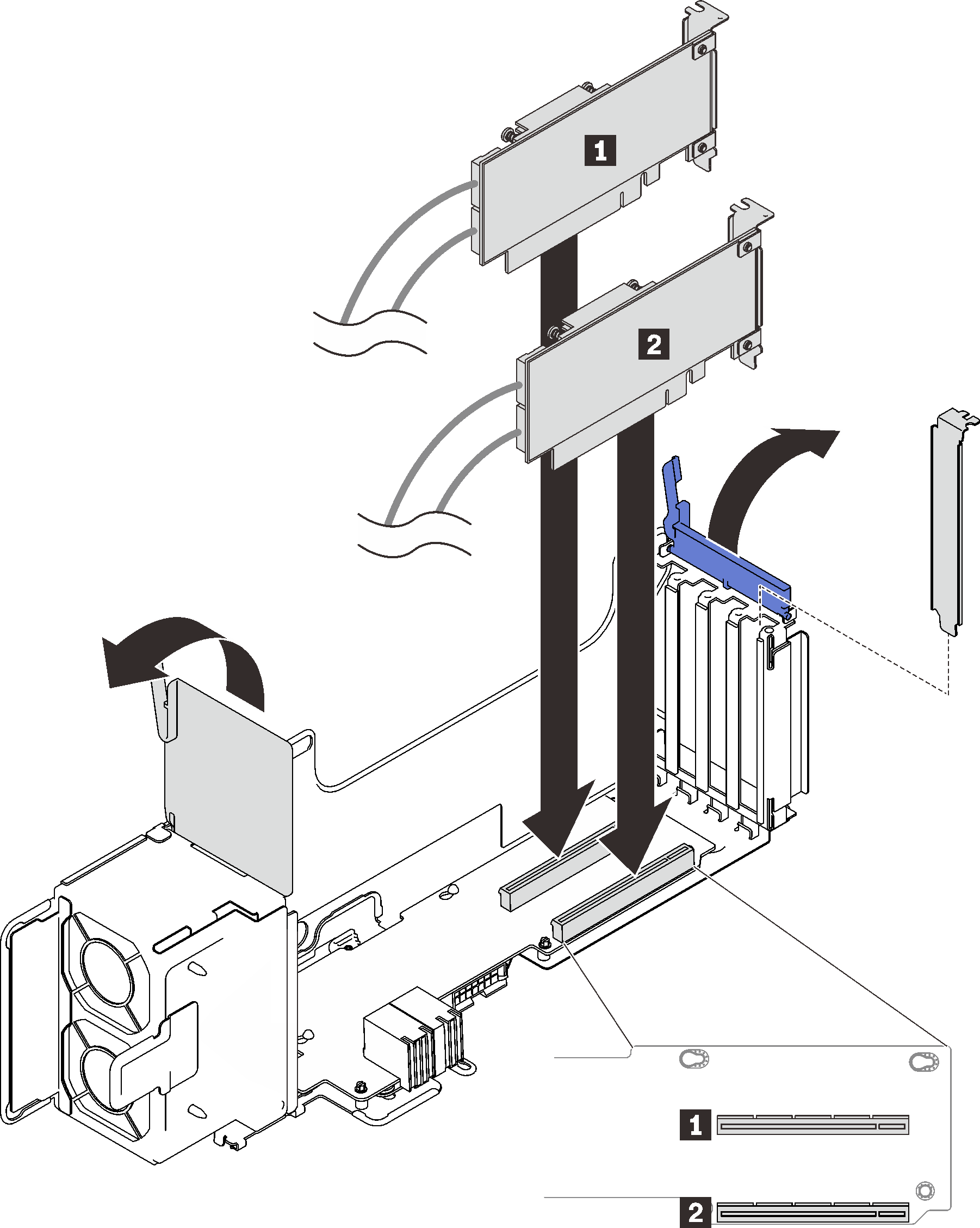
Then, close the retainers to secure the adapters.
Give documentation feedback