Connecting cables to the processor and memory expansion tray
Follow the instructions in this section to learn how to connect cables to the processor and memory expansion tray.
When working on cable routing plans that involve the processor and memory expansion tray, perform the procedure in the following order.
- Connect the following:
- Connect all the cables in the plan to corresponding drive backplanes.
- Connect all the SAS/SATA cables to the adapters or the on-board SAS/SATA connector.
- If applicable, connect the two PCIe cables to the connectors on the system board.
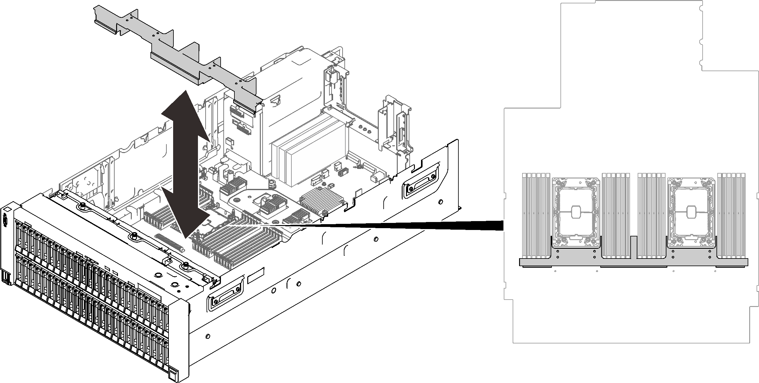
- Install the expansion tray air baffle.Figure 1. Installing the expansion tray air baffle
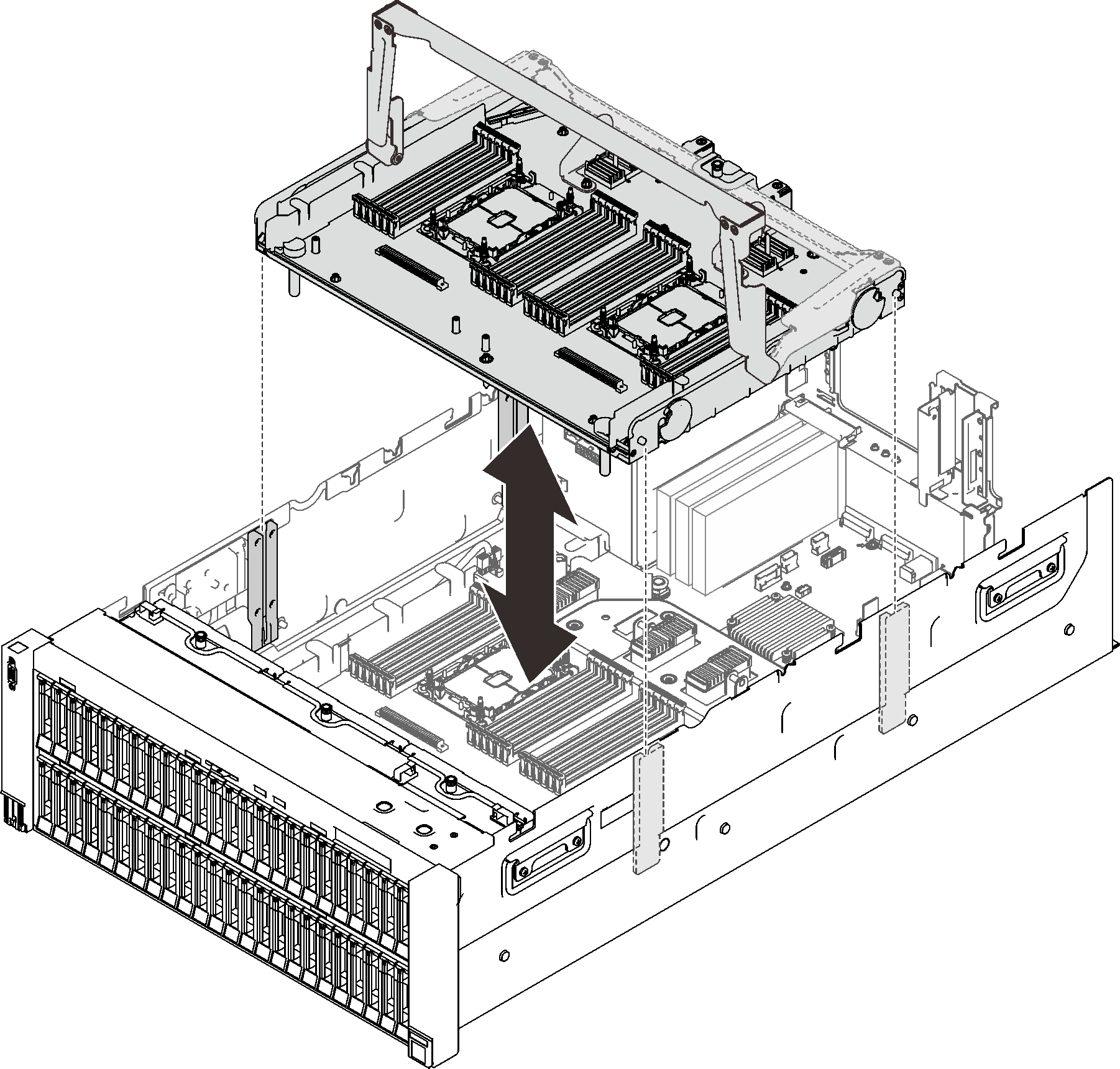
- Align the processor and memory expansion tray with the two pairs of guides on the sides, and lower it into the chassis.Figure 2. Installing the processor and memory expansion tray
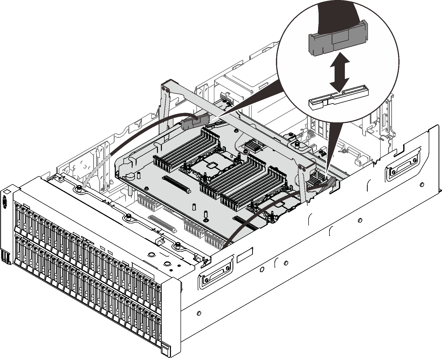
- Route the two PCIe cables through the side cable guides, and connect them to the processor and memory expansion tray.Figure 3. Connecting cables to the expansion tray
- Secure the processor and memory expansion tray.Figure 4. Securing the processor and memory expansion tray
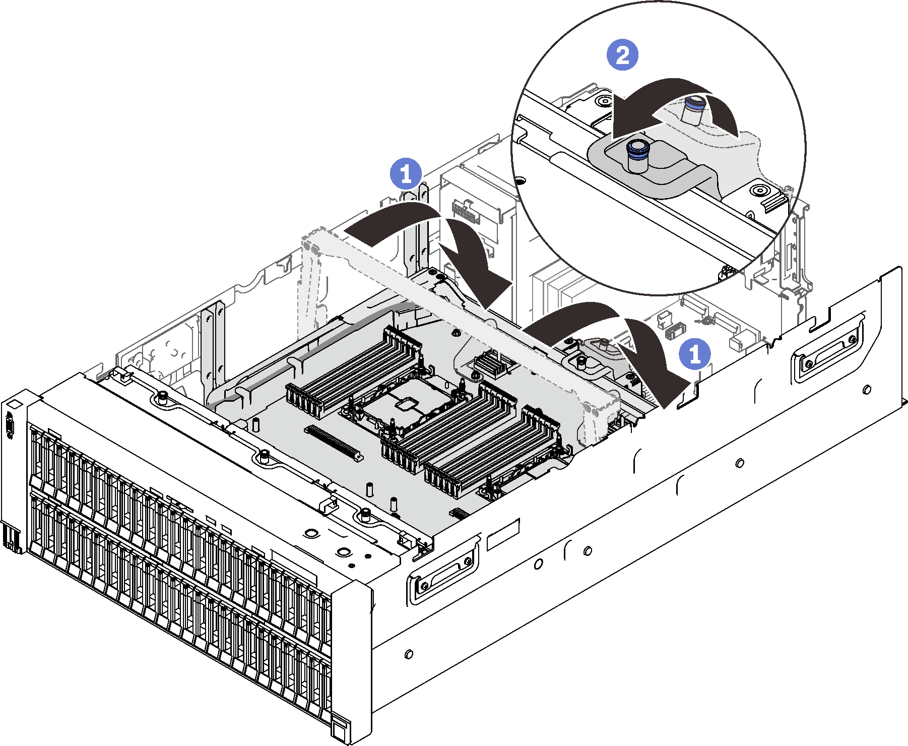
 Rotate the handle all the way down. This connects and fixes the expansion tray to the system board.
 Pull the retaining tab back to secure the handle.
Give documentation feedback