Remove the USB front panel module
Follow instructions in this section to remove the USB front panel module.
About this task
Attention
Go over Installation Guidelines to ensure that you work safely.
Turn off the server and peripheral devices and disconnect the power cords and all external cables (see Power off the server).
If the server is installed in a rack, slide the server out on its rack slide rails to gain access to the top cover, or remove the server from the rack.
Procedure
- Disconnect the USB front panel cable from the system board.AttentionTo avoid damaging the system board, make sure to follow the instructions in
Internal cable routing when disconnecting cables from the system board. Figure 1. Disconnecting the USB front panel cable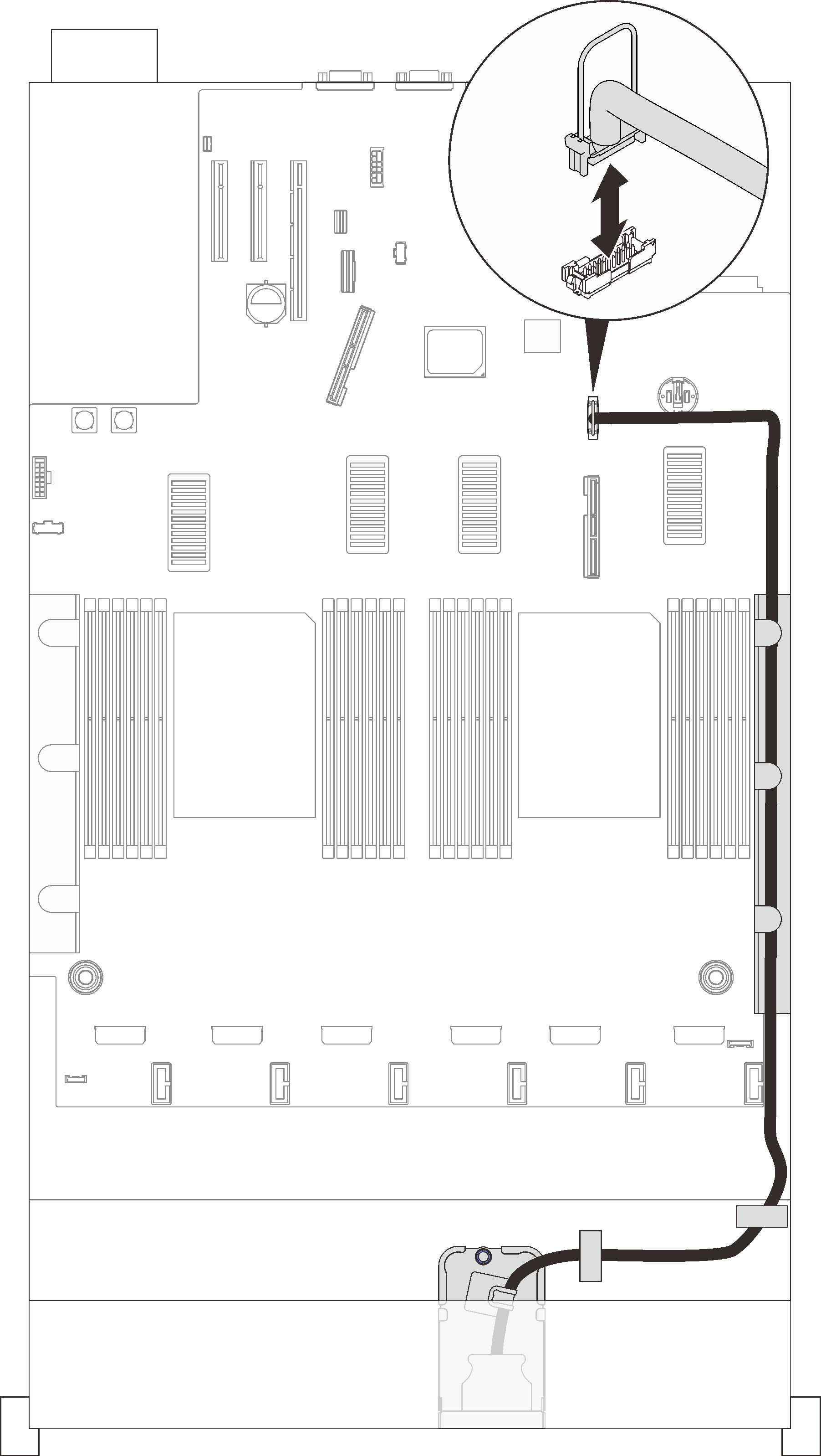
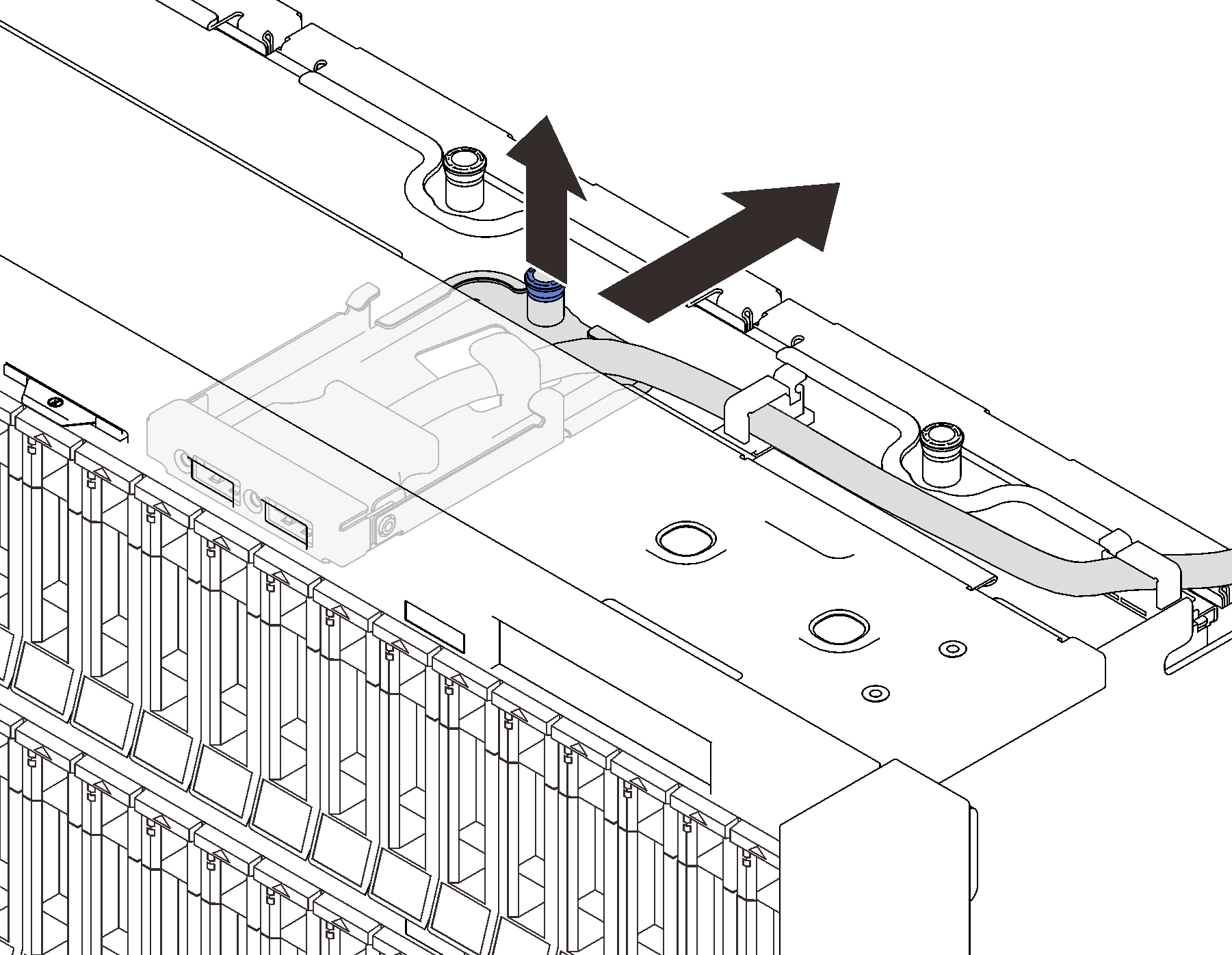
- Pull the captive screw up to disengage the module, and remove it from the server.Figure 2. Removing the USB front panel assembly
After this task is completed
- Install a replacement unit (see Install the USB front panel module).
If you are instructed to return the component or optional device, follow all packaging instructions, and use any packaging materials for shipping that are supplied to you.
Demo video
Give documentation feedback