Remove the system board
Use this information to remove the system board.


If the server is in a rack, remove it from the rack.
Remove any locking device that secures the server cover, such as a Kensington lock or a pad lock.
Remove the server cover (see Remove the server cover).
Make note of where the cables are connected to the system board; then, disconnect all the cables.
AttentionDisengage all latches, cable clips, release tabs, or locks on cable connectors beforehand. Failing to release them before removing the cables will damage the cable connectors on the system board. Any damage to the cable connectors may require replacing the system board.- Remove any of the following components that are installed on the system board and put them in a safe, static-protective place. See the related topics in Hardware replacement procedures.
Front and rear system fans
PCIe adapters
DIMMs
Heat sink and fan assembly
Processor
CMOS battery
M.2 backplane
TPM card (for Chinese Mainland only)
To remove the system board, complete the following steps:
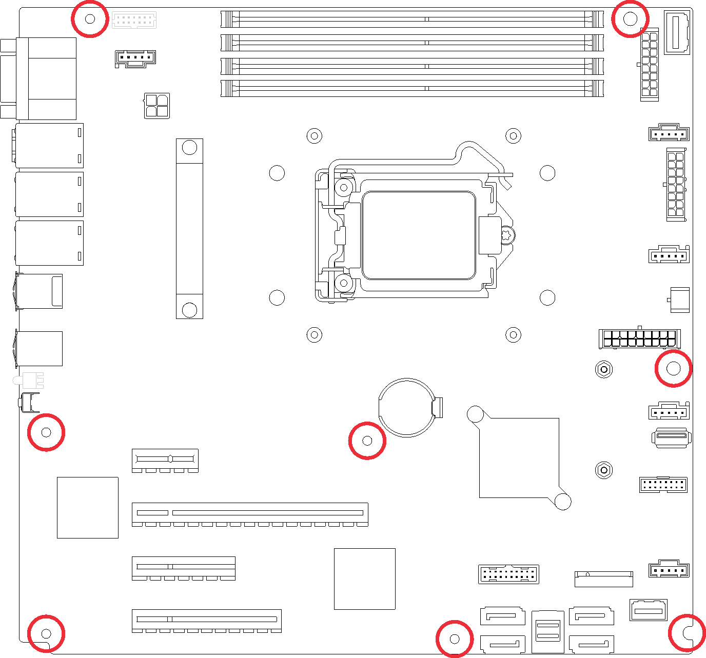
- Remove the eight screws that secure the system board following the recommended numerical sequence as shown; then , carefully remove the system board out of the chassis.Figure 1. Screw removal that secures the system board
After removing the system board:
If you are instructed to return the defective component, please package the part to prevent any shipping damage. Reuse the packaging the new part arrived in and follow all packaging instructions.
Take a dust cover from the processor socket assembly on the new system board and orient it correctly above the processor socket assembly on the removed system board.
Gently press down the dust cover legs to the processor socket assembly, pressing on the edges to avoid damage to the socket pins. You might hear a click on the dust cover is securely attached.
Make sure that the dust cover is securely attached to the processor socket assembly.
Demo video