System board components
The illustration in this section shows the component locations on the system board.
Figure 1. System board components
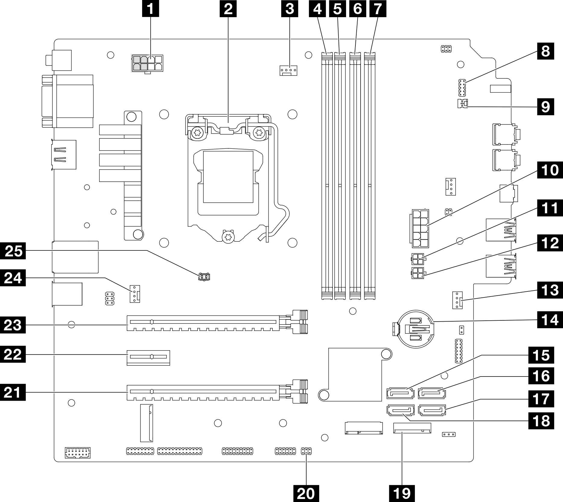
| 1 Processor power connector Note The 2x2 pins marked in grey are for 300W PSU. | 14 3V battery (CR2032) |
| 2 Processor | 15 SATA 3 connector (drive bay 3) |
| 3 Processor heat sink fan power connector | 16 SATA 4 connector (ODD drive) |
| 4 Memory module slot 1 | 17 SATA 2 connector (drive bay 2) |
| 5 Memory module slot 2 | 18 SATA 1 connector (drive bay 1) |
| 6 Memory module slot 3 | 19 M.2 connector |
| 7 Memory module slot 4 | 20 Thermal sensor connector |
| 8 Power button with LED connector | 21 PCIe slot 3 (PCI Express 3.0 x4 ) |
| 9 Mono amplifier (speaker) connector | 22 PCIe slot 2 (PCI Express 3.0 x1) |
| 10 System power connector | 23 PCIe slot 1 (PCI Express 4.0 x16) |
| 11 SATA power 1 connector | 24 Rear fan connector |
| 12 SATA power 2 connector | 25 Intrusion switch connector |
| 13 Front fan connector |
Give documentation feedback