Rear view
This section contains information about the important components on the rear of this server.
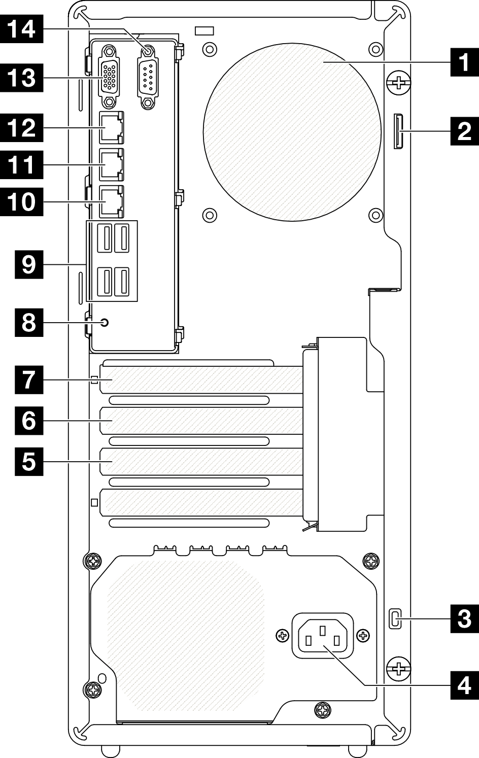
| 1 Rear fan | 8 NMI button |
| 2 Padlock loop | 9 USB 3.2 Gen 1 (5 Gbps) connectors (total of four connectors) |
| 3 Kensington lock | 10 Ethernet connector 2 |
| 4 Power cord connector | 11 Ethernet connector 1 (shared with XCC network port) |
| 5 PCIe slot 3 | 12 XCC system management port (10/100/1000 Mbps RJ-45) |
| 6 PCIe slot 2 | 13 VGA connector |
| 7 PCIe slot 1 | 14 Serial port |
1 Rear fan
Install the rear fan in this space.
2 Padlock loop
This loop is available for installing a padlock. See Server locks for more information.
3 Kensington lock
This loop is available for installing a Kensington lock. See Server locks for more information.
4 Power cord connector
Connect the power cord to this component.
5/6/7 PCIe slots
There are three PCIe slots on the system board to install appropriate PCIe adapters. For information about the PCIe slots, see Specifications.
8 NMI button
Press this button to force a nonmaskable interrupt to the processor. You might have to use a pen or the end of a straightened paper clip to press the button. You can also use it to force a blue-screen memory dump. Use this button only when you are directed to do so by Lenovo Support.
9 USB 3.2 Gen 1 (5 Gbps) connectors
There are four USB 3.2 Gen 1 (5 Gbps) connectors on the rear of the server. Connect a USB device, such as a mouse, keyboard, or other devices, to either of these connectors.
10 Ethernet connector 2
Attach an Ethernet cable for LAN. Each Ethernet connector has two status LEDs to help you identify the Ethernet connectivity and activity.
11 Ethernet connector 1 (shared with XCC network port)
Attach an Ethernet cable for LAN. Each Ethernet connector has two status LEDs to help you identify the Ethernet connectivity and activity. If the LOM adapter is not installed, Ethernet connector 1 can be set as Lenovo XClarity Controller Network connector.
To set Ethernet connector 1 as Lenovo XClarity Controller Network connector, start Setup Utility and select . Then, click Shared NIC on and select Share OnLom Port:01.
12 XCC system management port (10/100/1000 Mbps RJ-45)
The server has a 10/100/1000 Mbps RJ-45 connector dedicated to Lenovo XClarity Controller (XCC) functions. Through the system management port, you can access the Lenovo XClarity Controller directly by connecting your laptop to the management port using an Ethernet cable. Make sure that you modify the IP settings on the laptop so that it is on the same network as the server default settings. A dedicated management network provides additional security by physically separating the management network traffic from the production network.
13 VGA connector
14 Serial connector
Connect a 9-pin serial device to this connector. The serial port is shared with XCC. XCC can take control of the shared serial port to redirect serial traffic, using Serial over LAN (SOL).