Remove the system board (trained technician only)
Follow this procedure to remove the system board. This procedure must be executed by a trained technician.


Read the safety information and installation guidelines (see Safety and Installation guidelines).
Record all the settings in the Setup Utility, as you might have to re-enter these settings after replacing the system board.
Turn off the server and peripheral devices, and disconnect the power cords and all external cables (see Power off the server).
If the server is in a rack, remove it from the rack.
Remove any locking device that secures the server cover, such as a Kensington lock or a pad lock.
- Remove the server cover (see Remove the server cover).CAUTIONThe heat sinks and processor could be very hot. To avoid from burning yourself, wait for a few minutes after turning off the server before you remove the server cover.
Place the server on its side with the cover up.
- Disconnect all the cables connected to the system board.AttentionDisengage all latches, cable clips, release tabs, or locks on cable connectors beforehand. Failing to release them before removing the cables will damage the cable connectors on the system board. Any damage to the cable connectors may require system board replacement.Attention
To avoid damaging the system board, make sure to follow the instructions in Internal cable routing when disconnecting cables from the system board.
Remove all the PCIe adapters (see Remove a PCIe adapter).
Remove all the DIMMs (see Remove a DIMM).
To remove the system board, complete the following steps:
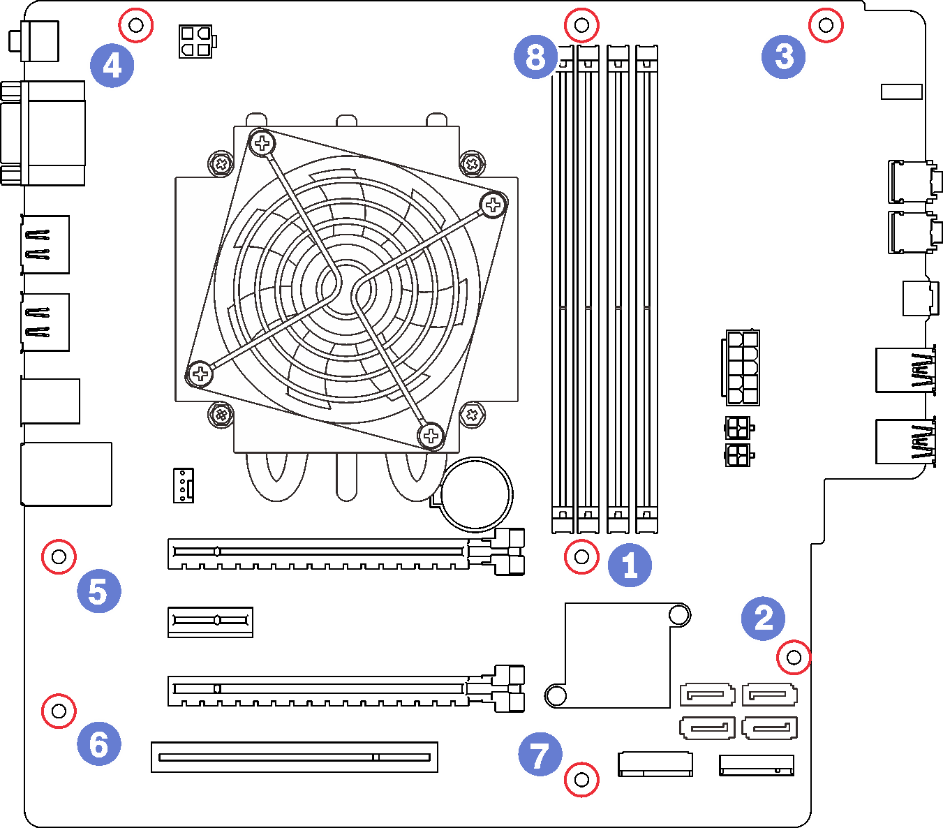
- Remove the eight screws that secure the system board in the order as illustrated, and keep them for future use.Figure 1. System board screw removal sequence
After removing the system board:
Remove the heat sink and fan module and the processor if necessary (see Remove the heat sink and fan module and Remove the processor).
Install another system board (see Install the system board (trained technician only)).
If you are instructed to return the component or optional device, follow all packaging instructions, and use any packaging materials for shipping that are supplied to you.
Demo video