Front panel
Some crucial key controls, connectors, and LEDs are located on the front panel of the server.
The following illustration shows the controls, connectors, and LEDs on the front panel of the server.
Figure 1. Components on the front panel
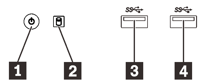
| 1 Power button with power status LED (green) | 3 USB 3.1 Gen1 connector |
| 2 Drive activity LED (green) | 4 USB 3.1 Gen1 connector |
1 Power button with power status LED (green)
Press the power button to turn on the server, or hold it for several seconds to turn the server off when the server cannot be turned off in the operating system. The power status LED helps determine the current power status.
| Status | Color | Description |
|---|---|---|
| Solid on | Green | DC power is present and the server is on. |
| Off | None | No DC power is present and the server is off. |
2 Drive activity LED (green)
This LED indicates the activity of the drives.
| Status | Color | Description |
|---|---|---|
| Solid on | Green | The drives are active. |
| Off | None | The drives are not active. |
Note
The drive activity LED only indicates the activities of drives that are connected to the SATA ports on the system board.
3 4 USB 3.1 Gen1 connectors
Available for a device that require USB 2.0 or 3.0 connection, such as a keyboard, a mouse, or a USB flash drive.
Give documentation feedback