Server models with eight 3.5-inch simple-swap drives
Use this section to understand the cable routing for server models with eight 3.5-inch simple-swap drives.
Note
Ensure that all cables are routed through the correct cable clips.
Figure 1. Cable routing for server models with eight 3.5-inch simple-swap drives
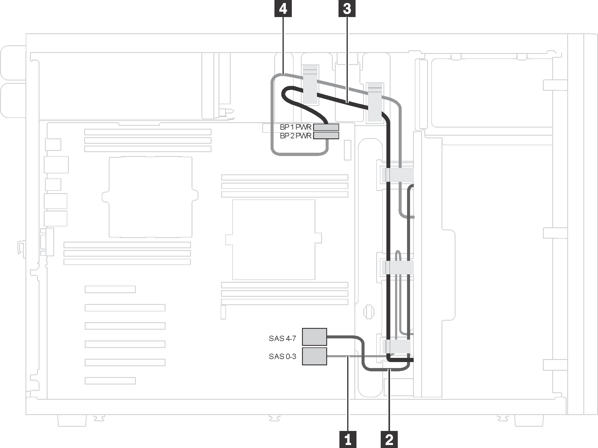
| From | To |
|---|---|
| 1 Signal cable on backplate 1 | SAS 0–3 connector on the system board |
| 2 Signal cable on backplate 2 | SAS 4–7 connector on the system board |
| 3 Power cable on backplate 1 | Backplane 1 power connector on the system board |
| 4 Power cable on backplate 2 | Backplane 2 power connector on the system board |
Give documentation feedback