Deploy the Linux Appliance Instance
Create an application instance from a template that will be used as the NFV.
- Click New Instance next to the CentOS 7.5 (64-bit) - Lenovo Template.Figure 1. CentOS 7.5 (64-bit) Template
 Note
NoteIf the template is not displayed in Organization Templates, you can download it from the Lenovo Cloud Marketplace. For more information, see the following topic:
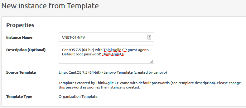
- Enter a name in the Instance Name field under the Properties section (for example, VNET-01-NFV).Figure 2. New Instance Name
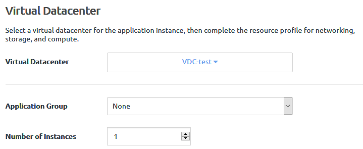
- In the Virtual Datacenter section, select the virtual datacenter where the application instance will run. This selection determines the migration zone and storage pool resources available for the application instance. Use the virtual datacenter (VDC-test) that was assigned to the VNET VNET-ID-01 when it was created.Figure 3. Virtual Datacenter assignment
- Configure the network as follows:
- Assign vNIC 0 to the Hypervisor VLAN (for example: Default 4091).
- Add a second vNIC by clicking Add vNIC.
- Assign vNIC 1 to VNET-ID-01.
Figure 4. Modify Network Settings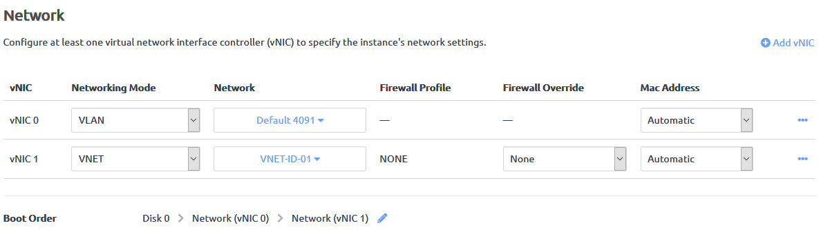
- Click the Profile tab and navigate to the Networking section. Click the Actions menu (
 ) next to each vNIC and click Edit Name.Figure 5. vNIC Edit Name
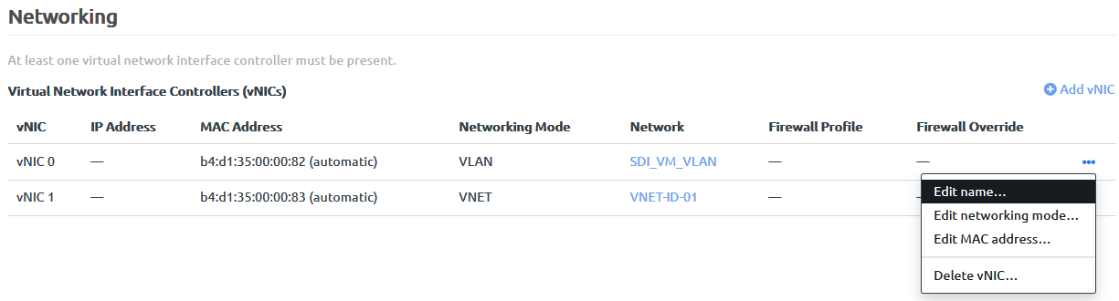
- Rename vNIC 0 to be outside.
- Rename vNIC 1 to be inside.
Figure 6. vNIC after renaming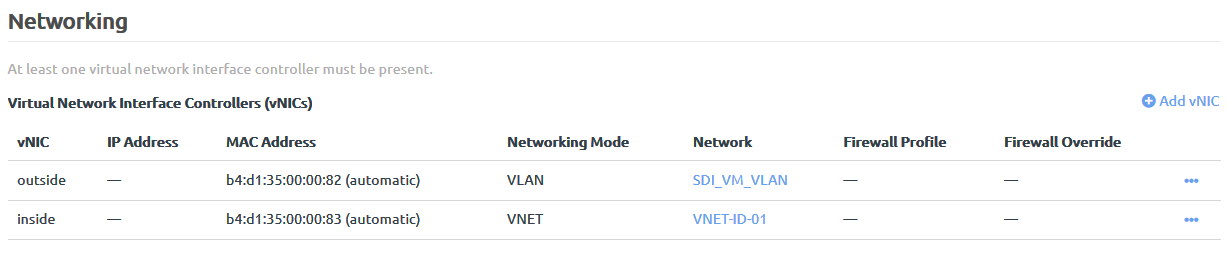
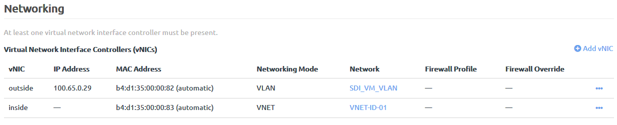
- Record the MAC addresses for both vNICs for later use, as well as the IP address that was allocated to the outside vNIC.Figure 7. IP and MAC Addresses
Give feedback