Install the ThinkAgile CP interconnect switch
Procedures for installing ThinkAgile CP interconnect switch in a rack.
The switch drawings in this topic are for illustration only and may not match your specific switch model.
If you are using a non-Lenovo switch as the management switch, keep 1U of empty space between the interconnect switches and the management switch so that power or network cables can use this space.
To install the ThinkAgile CP interconnect, do the following:
When installing two interconnects, make sure that you install the secondary interconnect lower in the rack than the primary interconnect. The secondary interconnect is labeled with a rack location label that is lower than the rack location label of the primary interconnect.
- Unpack the switch and check the contents.
Component Description 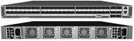
7Y67 switch

Rack mounting kit
2 front-post brackets
2 rear-post brackets
20 screws
2 ear-locking screws

Console cable, RJ-45 to DB-9
CAUTIONThe switch includes plug-in power supply (PSU) and fan tray modules that are installed into its chassis. All installed modules must have a matching airflow direction. That is, if the installed power modules have a front-to-back (F2B) airflow direction, all the installed fan tray modules must also have an F2B airflow direction.
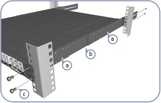
- Attach the brackets.
 CAUTION
Installing the switch in a rack requires two people. One person should position the interconnect switch in the rack, while the other secures it using the rack screws.
- Attach each of the rails to the interconnect switch using four of the included rail screws.
- Use an additional two screws to secure each of the rails at the midpoint on the sides of the interconnect switch.
- Use the screws and cage nuts supplied with the rack to secure the switch in the rack.
NoteMake sure that you attach the cage nuts to the rack before installing the interconnect switch.
- Adjust the rear-post rail flange and then lock the position of the rear-post rail flange using the included position-locking screws.
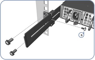 Note
NoteYou can also adjust the rear-post rail flange to fit different rack depths from 56 cm to 75 cm.
- Ground the interconnect switch.
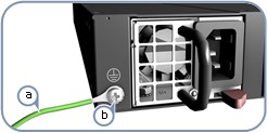
- Connect the power.
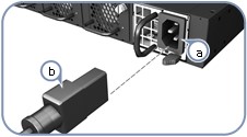
- Install one or two AC power modules in the switch. The switch supports up to two PSUs that must have the same matching airflow direction as the installed fan tray.
- Connect an external AC power source to the modules.
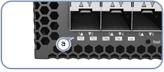
- Verify basic switch operation by checking the system LEDs. When operating normally, the PSU1/PSU2, Diag, and Fan LEDs should all be green.
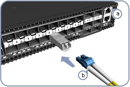
- Connect the network cables.
- View the product label. The switch product label is located below SFP+ ports 7–12 on left side of the front panel. Pull the label out to view the product information.
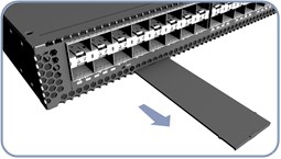
The installation of the interconnect switch is now complete.