Installing a ServeRAID adapter
Use this information to install a ServeRAID adapter
For information about the types of ServeRAID adapters that the server supports and other information that you might consider when you install an ServeRAID adapter, see the Installation and User’s Guide. (For the locations of the expansion slots and connectors, see System-board internal connectors).
To install a replacement ServeRAID adapter on 4U server models with non-hot-swap power supplies, complete the following steps. For the 5U server model with hot-swap power supplies (Model name: 2582-F4x), please see the next sub-section.
- Read the safety information in Safety and Installation guidelines.
- Check the instructions that come with the adapter for any requirements, restrictions, or cabling instructions. It might be easier to route cables before you install the adapter.
- Follow the instructions that come with the adapter to set jumpers or switches, if any.
- Touch the static-protective package that contains the adapter to any unpainted metal surface on the server. Then, remove the adapter from the static-protective package. Avoid touching the components and gold-edge connectors on the adapter.
- Turn off the server and all peripheral devices; then, disconnect the power cords and all external cables.
- Carefully turn the server on its side so that it is lying flat, with the cover facing up.AttentionDo not allow the server to fall over.
- Remove the side cover (see Removing the side cover).
- Remove the air duct.
- Follow the cabling instructions, if any, that come with the adapter. Route the adapter cables before you install the adapter.
- Follow the instructions that come with the adapter to set jumpers or switches, if any.
- Lift the end of the rear adapter retention bracket till the tab disengages the hole on the chassis.
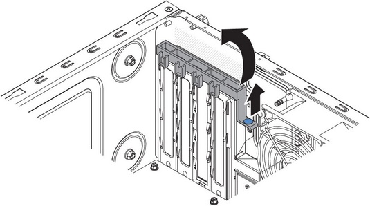
- Rotate the rear adapter retention bracket upward to remove it from the chassis.
- Remove the screw that secures the expansion-slot cover to the chassis. Store the expansion-slot cover and screw in a safe place for future use.NoteExpansion-slot covers must be installed on all vacant slots. This maintains the electronic emissions standards of the server and ensures proper ventilation of server components.
- Touch the static-protective package that contains the adapter to any unpainted metal surface on the server. Then, remove the adapter from the static-protective package. Avoid touching the components and gold-edge connectors on the adapter.
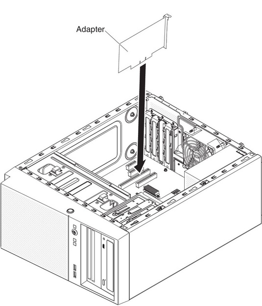
- Carefully grasp the adapter by the top edge or upper corners, and align it with the expansion slot guides; then, press the adapter firmly into the expansion slot. Make sure that the adapter is correctly seated in the expansion slot before you turn on the server. Incomplete installation of an adapter might damage the system board or the adapter.AttentionMake sure that the adapter is correctly seated in the expansion slot before you turn on the server. Incomplete installation of an adapter might damage the system board or the adapter.
- Position the rear adapter retention bracket so that the hole in one of the hinge points is aligned with the hinge pin on the chassis; then, place the hinge pin through the hole on the chassis.
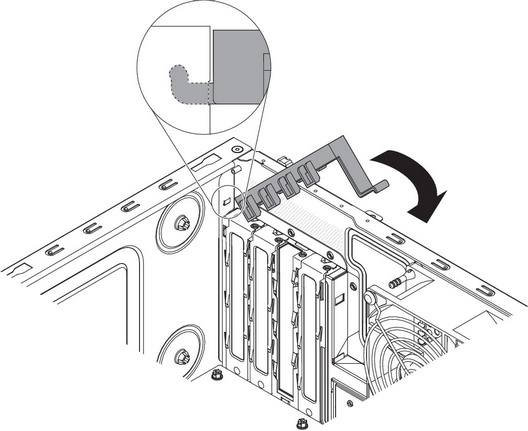
- Rotate the rear adapter retention bracket into place so that the hole in the opposite hinge point snaps into place over the hinge pin on the chassis.
- Connect any required cables to the adapter. Route the cables so that they do not block the flow of air from the system fan.
- Install the air duct.
If you have other devices to install, do so now. Otherwise, go to Completing the installation.
To install a replacement ServeRAID adapter on the 5U server model with hot-swap power supplies (Model name: 2582-F4x), complete the following steps. For 4U server models with non-hot-swap power supplies, please see the above sub-section.
- Read the safety information in Safety and Installation guidelines.
- Check the instructions that come with the adapter for any requirements, restrictions, or cabling instructions. It might be easier to route cables before you install the adapter.
- Follow the instructions that come with the adapter to set jumpers or switches, if any.
- Touch the static-protective package that contains the adapter to any unpainted metal surface on the server. Then, remove the adapter from the static-protective package. Avoid touching the components and gold-edge connectors on the adapter.
- Turn off the server and all peripheral devices; then, disconnect the power cords and all external cables.
- Unlock and remove the side cover (see Removing the side cover).
- Carefully turn the server on its side so that it is lying flat, with the system board facing up.AttentionDo not allow the server to fall over.
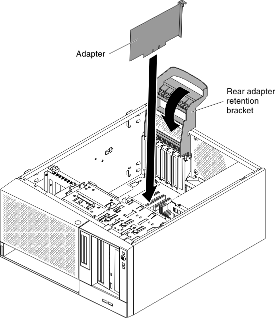
- Rotate the rear adapter-retention bracket to the open (unlocked) position.
- Carefully grasp the adapter by the top edge or upper corner, and move the adapter directly from the static-protective package to the expansion slot. Align the adapter with the expansion slot guides; then, press the adapter firmly into the expansion slot.
- Connect the required cables to the adapter. Route cables so that they do not block the air flow from the fan.
- Position the rear adapter retention bracket so that the hole in one of the hinge points is aligned with the hinge pin on the chassis; then, place the hinge pin through the hole on the chassis.
If you have other devices to install, do so now. Otherwise, go to Completing the installation.