Installing the thermal solution fan kit
Use this information to install the thermal solution fan kit
Attention
- To ensure proper cooling and airflow, do not operate the server for more than 30 minutes with the side cover removed.
- When you install a second adapter in the adapter slots on the system board, you must install the Lenovo Thermal Solution Fan kit option to ensure proper cooling and airflow to the system. For 4U server models with non-hot-swap power supplies, the part number is 46W9177. For 5U server models with hot-swap power supplies, the part number is 00Y8200.
To install the thermal solution fan kit on 4U server models with non-hot-swap power supplies, complete the following steps. For the 5U server model with hot-swap power supplies, please see the next sub-section.
- Read the safety information in Safety and Installation guidelines.
- Turn off the server and all attached devices; then, disconnect all power cords and external cables.
- Carefully turn the server on its side so that it is lying flat, with the cover facing up.AttentionDo not allow the server to fall over.
- Remove the side cover (see Removing the side cover).
- Remove the air baffle (see Removing the air baffle).
- Follow any special handling and installation instructions that come with the thermal solution fan kit.
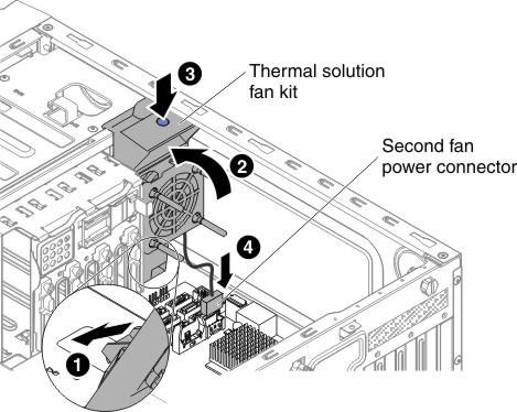
- Insert the thermal solution fan kit:
- Grasp the system fan by the blue point and lower it into the server, making sure that it latches on to the chassis.
- Connect the fan cable to the system board (see System-board internal connectors).Figure 1. Thermal solution fan kit installation for 4U server model with non-hot-swap power supplies
- If you have other devices to install, do so now. Otherwise, go to Completing the installation.
To install the thermal solution fan kit on 5U server models with hot-swap power supplies, complete the following steps. For the 4U server model with non-hot-swap power supplies, please see the above sub-section.
- Read the safety information in Safety and Installation guidelines.
- Turn off the server and all attached devices; then, disconnect all power cords and external cables.
- Unlock and remove the side cover (see Removing the side cover).
- Carefully turn the server on its side so that it is lying flat, with the cover facing up.AttentionDo not allow the server to fall over.
- Insert the thermal solution fan kit:Figure 2. Thermal solution fan kit installation for 5U server model with hot-swap power supplies
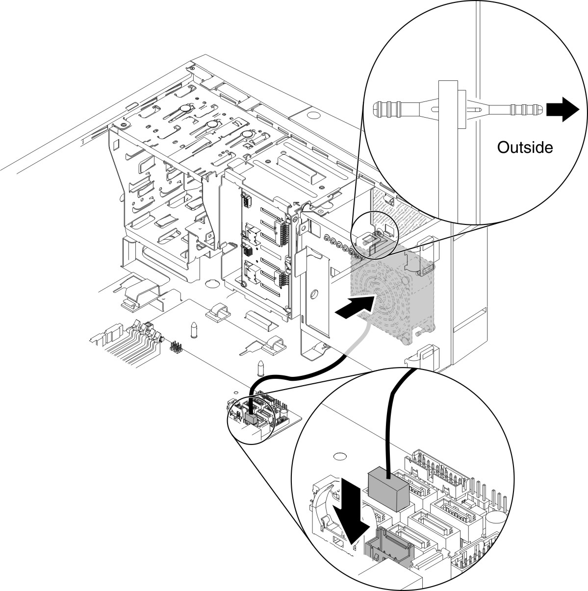
- Position the fan so that the grommets protrude through the holes in the chassis; then, use needle-nosed pliers to pull the grommets through the holes from outside the chassis.
- Connect the fan cable into the system board (see System-board internal connectors).
- If you have other devices to install, do so now. Otherwise, go to Completing the installation.
Give documentation feedback