Installing a microprocessor and heat sink
Use this information to install a microprocessor and heat sink
To install the microprocessor and heat sink on 4U server models with non-hot-swap power supplies, complete the following steps. For the 5U server model with hot-swap power supplies, please see the next sub-section.
- Read the safety information in Safety and Installation guidelines.
- Turn off the server and all attached devices; then, disconnect all power cords and external cables.
- Carefully turn the server on its side so that it is lying flat, with the cover facing up.AttentionDo not allow the server to fall over.
- Remove the side cover (see Removing the side cover).
- Remove the air baffle (see Removing the air baffle).
- Touch the static-protective package that contains the microprocessor to any unpainted metal surface on the server. Then, remove the microprocessor from the package.
- Remove the protective cover, tape, or label from the surface of the microprocessor socket, if any is present.
- Rotate the release lever on the microprocessor socket to the fully open position.AttentionMake sure that the release lever on the microprocessor socket is in the fully open position before you insert the microprocessor in the socket. Failure to do so might result in permanent damage to the microprocessor, microprocessor socket, and system board.
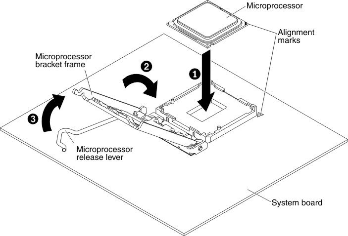
- Carefully grasp the microprocessor and place the microprocessor into the microprocessor socket.NoteTo maintain correct orientation between the microprocessor and the microprocessor socket during installation, observe the following information:
- The microprocessor has two notches that are keyed to two tabs on the sides of the socket.
- A triangle-shaped indicator on one corner of the microprocessor points to a 45-degree angle on the system board.
- Do not use excessive force when you press the microprocessor into the socket.
- Close the microprocessor bracket frame; then, close the microprocessor retention latch and lock it securely in place.Figure 1. Microprocessor bracket frame and retention latch engagement for 4U server models with non-hot-swap power supplies
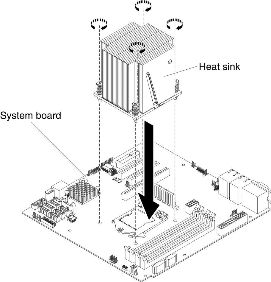
- Install the heat sink:AttentionTo maintain correct orientation between the microprocessor and the microprocessor socket during installation, observe the following information:
- Align the screw holes on the heat sink with the holes on the system board.
- Tighten the screws with a screwdriver, alternating among the screws until they are tight. If possible, each screw should be rotated two full rotations at a time. Repeat until the screws are tight. Do not overtighten the screws by using excessive force.ImportantDo not touch the thermal material on the bottom of the heat sink. Touching the thermal material will contaminate it. If the thermal material on the microprocessor or heat sink becomes contaminated, contact your service technician.Figure 2. Heat sink installation for 4U server models with non-hot-swap power supplies
- Reconnect any cables that you disconnected during the removal of the old microprocessor.
- Secure the SATA signal cables with the retention-clips.
- Install the air baffle (see Replacing the air baffle).
If you have other devices to install, do so now. Otherwise, go to Completing the installation.
To install the microprocessor and heat sink on the 5U server model with hot-swap power supplies, complete the following steps. For 4U server models with non-hot-swap power supplies, please see the above sub-section.
- Read the safety information in Safety and Installation guidelines.
- Turn off the server and all attached devices; then, disconnect all power cords and external cables.
- Unlock and remove the side cover (see Removing the side cover).
- Carefully turn the server on its side so that it is lying flat, with the system board facing up.AttentionDo not allow the server to fall over.
- Touch the static-protective package that contains the microprocessor to any unpainted metal surface on the server. Then, remove the microprocessor from the package.
- Remove the protective cover, tape, or label from the surface of the microprocessor socket, if any is present.
- Rotate the release lever on the microprocessor socket to the fully open position.AttentionMake sure that the release lever on the microprocessor socket is in the fully open position before you insert the microprocessor in the socket. Failure to do so might result in permanent damage to the microprocessor, microprocessor socket, and system board.
- Carefully grasp the microprocessor and place the microprocessor into the microprocessor socket.NoteTo maintain correct orientation between the microprocessor and the microprocessor socket during installation, observe the following information:
- The microprocessor has two notches that are keyed to two tabs on the sides of the socket.
- A triangle-shaped indicator on one corner of the microprocessor points to a 45-degree angle on the system board.
- Do not use excessive force when you press the microprocessor into the socket.
- Close the microprocessor bracket frame; then, close the microprocessor retention latch and lock it securely in place.Figure 3. Microprocessor bracket frame and retention latch engagement for 5U server models with hot-swap power supplies
- Install the heat sink:AttentionTo maintain correct orientation between the microprocessor and the microprocessor socket during installation, observe the following information:
- Align the screw holes on the heat sink with the holes on the system board.
- Tighten the screws with a screwdriver, alternating among the screws until they are tight. If possible, each screw should be rotated two full rotations at a time. Repeat until the screws are tight. Do not overtighten the screws by using excessive force.ImportantDo not touch the thermal material on the bottom of the heat sink. Touching the thermal material will contaminate it. If the thermal material on the microprocessor or heat sink becomes contaminated, contact your service technician.Figure 4. Heat sink installation for 5U server models with hot-swap power supplies
- Reconnect any cables that you disconnected during the removal of the old microprocessor. Rotate the rear adapter-retention bracket to the closed (locked) position.
If you have other devices to install, do so now. Otherwise, go to Completing the installation.
Give documentation feedback