Rear view
The following shows the connectors on the rear of the server.
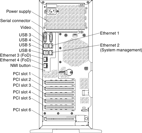
- NMI button: Press this button to force a nonmaskable interrupt to the microprocessor. It allows you to blue screen the server and take a memory dump (use this button only when directed by the Lenovo service support). You might have to use a pen or the end of a straightened paper clip to press the button.
- PCI-e slot 1: Insert a half-length, full-height PCI Express adapter or a PCI-X interposer card into this slot. See Installing an adapter for the supported adapters for these riser-cards.NoteIt only functional when the microprocessor 2 installed.
- PCI-e slot 2: Insert a full-length, full-height PCI Express adapter into this slot. See Installing an adapter for information about adapters that this riser card support.
- PCI-e slot 3: Insert a half-length, full-height PCI Express adapter into this slot. See Installing an adapter for information about adapters that this riser card support.
- PCI-e slot 4: Insert a full-length, full-height PCI Express adapter into this slot. See Installing an adapter for information about adapters that this riser card support.
- PCI-e slot 5: Insert a half-length, full-height PCI Express adapter into this slot. See Installing an adapter for information about adapters that this riser card support.
- PCI-e slot 6: Insert a half-length, full-height PCI Express adapter into this slot. See Installing an adapter for information about adapters that this riser card support.NoteIt has PCI-X capability by using PCI-e to PCI-X converter kit of Lenovo System x3500 M4 Type 7383.
- Power connector: Connect the power cord to this connector.
- Video connector: Connect a monitor to this connector.NoteThe maximum video resolution is 1600 x 1200 at 75 Hz.
- Serial connector: Connect a 9-pin serial device to this connector. The serial port is shared with the Integrated Management Module II (IMM2). The IMM2 can take control of the shared serial port to redirect serial traffic, using Serial over LAN (SOL).
- USB connectors: Connect a USB device, such as a USB mouse or keyboard to any of these connectors.
- Ethernet connectors: Use either of these connectors to connect the server to a network.
The following illustrations show the LEDs on the rear of the server.
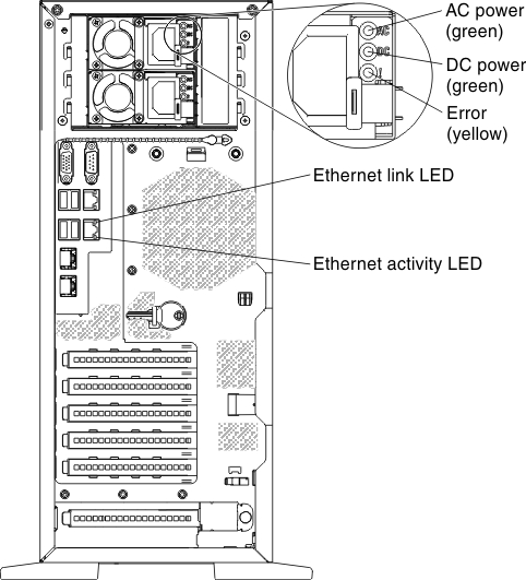
- AC power LED: Each power supply has an ac power LED. When the ac power LED is lit, it indicates that sufficient power is being supplied to the power supply through the power cord. During normal operation, both the ac and dc power LEDs are lit. For any other combination of LEDs, see Server controls, LEDs, and power.
- DC power LED: Each power supply has a dc power LED. When the dc power LED is lit, it indicates that the power supply is supplying adequate dc power to the system. During normal operation, both the ac and dc power LEDs are lit. For any other combination of LEDs, see Server controls, LEDs, and power.
- Power-supply error LED: When the power-supply error LED is lit, it indicates that the power supply has failed.NoteIn a redundant-Power supply system, the power supply 1 is the default/primary power supply. If power supply 1 fails, you must replace the power supply immediately.
- USB connectors: Connect a USB device to any of these connectors.
- Ethernet activity LEDs: When these LEDs are lit, they indicate that the server is transmitting to or receiving signals from the Ethernet LAN that is connected to the Ethernet port.
- Ethernet link LEDs: When these LEDs are lit, they indicate that there is an active link connection on the 10BASE-T, 100BASE-TX, or 1000BASE-TX interface for the Ethernet port.
- Ethernet connectors: Use either of these connectors to connect the server to a network. When you use the Ethernet 1 connector, the network can be shared with the IMM through a single network cable.
Give documentation feedback