When you replace the system board, you must either update the server with the latest firmware or restore the pre-existing firmware that the customer provides on a diskette or CD image. Make sure that you have the latest firmware or a copy of the pre-existing firmware before you proceed.
When you replace the system board, make sure that you remove the Integrated Management Module Advanced Upgrade and place it on the new system board. For information about the Advanced Upgrade, see Using the remote presence and blue-screen capture features.
Before you replace the system board, make sure that you back up any features on demand (FoD) keys that were enabled. Reactivate any Features on Demand features. Instructions for automating the activation of features and installing activation keys is in the Features on Demand User's Guide. To download the document, go to the Lenovo Features on Demand website, log in, and click Help.
To remove the system board, complete the following steps:
Turn off the peripheral devices and disconnect all power cords.
Note
When you replace the system board, you must either update the server with the latest firmware or restore the pre-existing firmware that the customer provides on a diskette or CD image. Make sure that you have the latest firmware or a copy of the pre-existing firmware before you proceed.
Pull the power supplies out of the rear of the server, just enough to disengage them from the server.
Remove the memory modules and set them aside on a static-protective surface for reinstallation (see Removing a memory module).
Note
Make a note of the location of each DIMM as you remove it, so that you can later reinstall it in the same connector.
(Trained technician only) Remove all heat sinks and microprocessors, and set them aside on a static-protective surface for reinstallation (see Removing a microprocessor and heat sink).
Note
Remove the socket covers from the microprocessor sockets on the new system board and place them on the microprocessor sockets of the system board you are removing.
Do not allow the thermal grease to come in contact with anything, and keep each heat sink paired with its microprocessor for reinstallation. Contact with any surface can compromise the thermal grease and the microprocessor socket. A mismatch between the microprocessor and its original heat sink can require the installation of a new heat sink.
Disconnect all cables from the system board. Make a list of each cable as you disconnect it; you can then use this as a checklist when you install the new system board.
Attention
Disengage all latches, release tabs or locks on cable connectors when you disconnect all cables from the system board. Failing to release them before removing the cables will damage the cable sockets on the system board. The cable sockets on the system board are fragile. Any damage to the cable sockets may require replacing the system board.
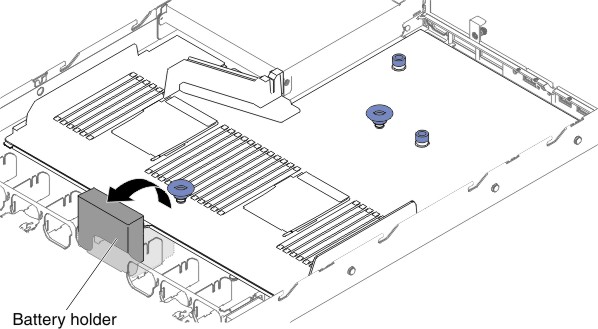
For 2.5-inch hard disk drive server models, open the system board retention lever. For the 3.5-inch hard disk drive server models, press the blue release tabs and lift the battery or power module holder upward.
Figure 1. Retention lever location for 2.5-inch hard disk drive server models
Figure 2. Battery or power module holder location for 3.5-inch hard disk drive server models
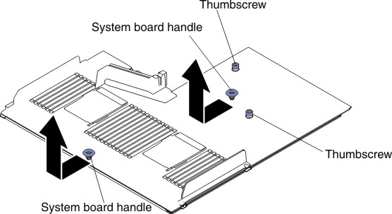
Loosen the two thumbscrews (one is near PCI slot 1 and one is near PCI slot 2).
Figure 3. Thumbscrews disengagement
Grasp the system board handles and slide the system board toward the front of the server until it stops.
Note
Make sure that the system board disengages from all system-board standoffs.
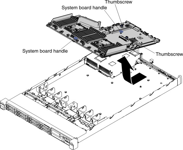
Slightly push the system board toward the hot-swap fans; then, grasp the system board handles and carefully lift it up from the chassis, being careful not to damage any surrounding components.
Figure 4. System board removal
Remove the socket covers from the microprocessor sockets on the new system board and place them on the microprocessor sockets of the old system board that you are removing.
If you are instructed to return the system board, follow all packaging instructions, and use any packaging materials for shipping that are supplied to you.
Attention
Make sure to place the socket covers for the microprocessor sockets on the system board before returning the system board.
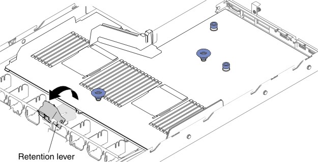 Figure 2. Battery or power module holder location for 3.5-inch hard disk drive server models