For service technician only: replacing the system board
Use this information to replace the system board.
Important
- When you reassemble the components in the server, be sure to route all cables carefully so that they are not exposed to excessive pressure.
- When you replace the system board, you must either update the server with the latest firmware or restore the pre-existing firmware from a diskette or CD image. Make sure that you have the latest firmware or a copy of the pre-existing firmware before you proceed. See Updating the firmware, Updating the Universal Unique Identifier (UUID), and Updating the DMI/SMBIOS data for more information.
- When you replace the system board, make sure that you remove the Integrated Management Module Advanced Upgrade and place it on the new system board. For information about the Advanced Upgrade, see Using the remote presence and blue-screen capture features.
- Reactivate any Features on Demand features. Instructions for automating the activation of features and installing activation keys is in the Features on Demand User's Guide. To download the document, go to the Lenovo Features on Demand website, log in, and click .
- Some cluster solutions require specific code levels or coordinated code updates. If the device is part of a cluster solution, verify that the latest level of code is supported for the cluster solution before you update the code.
To install the system board, complete the following steps:
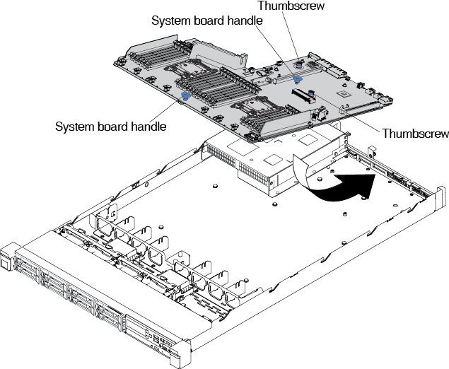
- Grasp the system board handles to align the system board with the chassis; then, lower the system board into the chassis and slide the system board toward the rear of the server until the system board is seated firmly into the locator pins on the chassis.Figure 1. System board installation
 NoteMake sure that all the system board standoffs engage the system board correctly.Figure 2. System-board standoffs
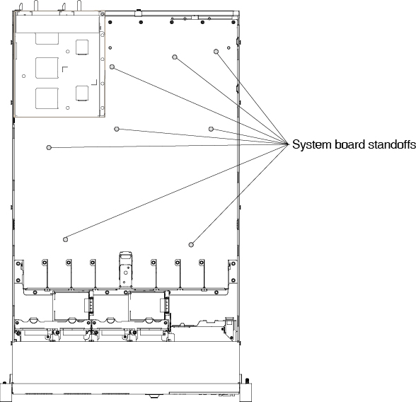
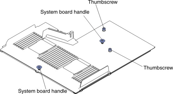
- Fasten the two thumbscrews (one is near PCI slot 2 and one is near the fan 5).Figure 3. Thumbscrews engagement
- For 2.5-inch hard disk drive server models, close the system board retention lever. For the 3.5-inch hard disk drive server models, press the blue release tabs and lower the battery or power module holder into the chassis.Figure 4. Retention lever location
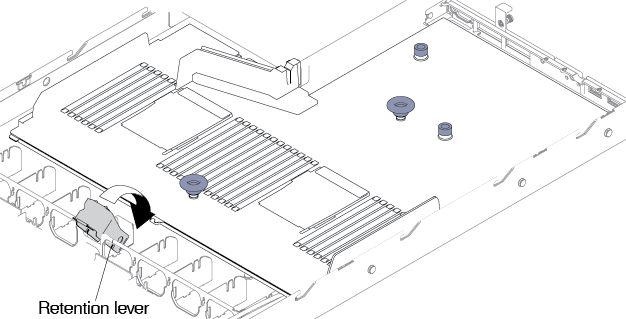 Figure 5. Battery or power module holder location for 3.5-inch hard disk drive server models
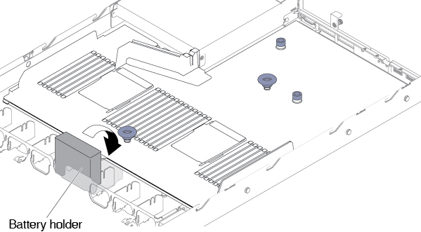
Give documentation feedback