Replacing an adapter
The following notes describe the types of adapters that the server supports and other information that you must consider when you install an adapter.
- Locate the documentation that comes with the adapter and follow those instructions in addition to the instructions in this section.
- The server provides one internal SAS/SATA RAID connector and two PCI slots on the system board. See System-board internal connectors for the location of the internal SAS/SATA RAID connector and riser-card slots. You can replace the ServeRAID SAS/SATA adapter with an optional ServeRAID SAS/SATA adapter in the slot. For configuration information, see the ServeRAID documentation at the Lenovo Support Portal.
- Do not set the maximum digital video adapter resolution above 1600 x 1200 at 75 Hz for an LCD monitor. This is the highest resolution that is supported for any add-on video adapter that you install in the server.
- Any high-definition video-out connector or stereo connector on any add-on video adapter is not supported
- The server does not support full-length, full-height PCI adapters or legacy 5V PCI adapters.
- When you install any PCI adapter, the power cords must be disconnected from the power source before you remove the PCI Express riser-card assembly. Otherwise, the active power management event signal will be disabled by the system-board logic, and the Wake on LAN feature might not work. However, after the server is powered-on locally, the active power manager active power management event signal will be enabled by the system-board logic.
The following adapters support 10-Gbps transfer rate only:
Intel X710 2x10GbE SFP+ Adapter
Intel X710 ML2 4x10GbE SFP+ Adapter
Intel X710-DA2 ML2 2x10GbE SFP+ Adapter
- Pay attention to the following before installing any PCI adapter.AttentionDo not install the NVIDIA Quadro K420, K600, or K620 adapter options in systems containing 1TB of system memory or more. If these options are installed in systems with 1TB of memory or more, it might cause undetected data corruption and system instability. These options are only supported in systems containing less than 1TB of memory. For more information, see RETAIN tip H213010 at
http://www.ibm.com/support/entry/myportal/docdisplay?lndocid=migr-5096047. - Pay attention to the following PCI adapter configuration table before installing any PCI adapter.
Table 1. Adapter configurations. Four column parts listing table for adapter description, option part number, PCI riser 1, and PCI riser 2.
Description Option part number PCI riser 1 PCI riser 2 QLogic 8200 Dual Port 10GbE SFP+ VFA 90Y4600 Seven fans required Seven fans required Intel X540 ML2 Dual Port 10GbaseT Adapter 00D1994 Seven fans required Seven fans required Lenovo 1250GB Enterprise Value io3 Flash Adapter for System x 00AE983 Seven fans required Seven fans required Lenovo 1600GB Enterprise Value io3 Flash Adapter for System x 00AE986 Seven fans required Seven fans required Lenovo 3200GB Enterprise Value io3 Flash Adapter for System x 00AE989 Seven fans required Seven fans required Lenovo 6400GB Enterprise Value io3 Flash Adapter for System x 00AE992 Not supported Seven fans required Lenovo 1000GB Enterprise io3 Flash Adapter for System x 00AE995 Seven fans required Seven fans required Lenovo 1300GB Enterprise io3 Flash Adapter for System x 00AE998 Seven fans required Seven fans required Lenovo 2600GB Enterprise io3 Flash Adapter for System x 00JY001 Seven fans required Seven fans required Lenovo 5200GB Enterprise io3 Flash Adapter for System x 00JY004 Not supported Seven fans required P3700 1.6TB NVMe Enterprise Performance Flash Adapter 00YA812 Seven fans required Seven fans required P3700 2.0TB NVMe Enterprise Performance Flash Adapter 00YA815 Seven fans required Seven fans required io3 1.25TB Enterprise Mainstream Flash Adapter 00YA800 Seven fans required Seven fans required io3 1.6TB Enterprise Mainstream Flash Adapter 00YA803 Seven fans required Seven fans required io3 3.2TB Enterprise Mainstream Flash Adapter 00YA806 Seven fans required Seven fans required io3 6.4TB Enterprise Mainstream Flash Adapter 00YA809 Not supported Seven fans required NoteYou can purchase the System x3550 M5 Fan Gen 2 (option part number: 00MV373) to acquire two additional fans for your server. - The server provides two PCI riser-card slots on the system board. The following information indicates the riser-card slots and the type of adapters that the riser cards support:
- If you want to install a PCI Express adapter, you must order the PCI riser-card option.
- PCI riser slot 1. This slot supports only low-profile or ML2 adapters.
- PCI riser slot 2. This slot supports full-height, half-length or low-profile adapters.
The following table lists the supported PCI riser-card assembly configurations in the server.Table 2. Configuration 1. The PCI riser-card assembly configuration 1 table description table.
Configuration 1 Configuration Number of microprocessors installed PCI riser-card assembly connector 1 on system board PCI riser-card assembly connector 2 on system board Slot 1 Slot 2 Slot 3 - Three low-profile slots
One x1/x4/x8/x16 low-profile x1/x4/x8 low-profile x1/x4/x8 low-profile Table 3. Configuration 2. The PCI riser-card assembly configuration 2 table description table.
Configuration 2 Configuration Number of microprocessors installed PCI riser-card assembly connector 1 on system board PCI riser-card assembly connector 2 on system board Slot 1 Slot 2 Slot 3 - Three low-profile slots
Two x1/x4/x8/x16 low-profile x1/x4/x8/x16 low-profile x1/x4/x8/x16 low-profile Table 4. Configuration 3. The PCI riser-card assembly configuration 3 table description table.
NoteSlot 1 is for the 60-mm ML2 adapter.Configuration 3 Configuration Number of microprocessors installed PCI riser-card assembly connector 1 on system board PCI riser-card assembly connector 2 on system board Slot 1 Slot 2 Slot 3 - One ML2 slot
- One full-height, half-length slot
- One low-profile slot
One ML2 x1/x4/x8 full-height, half-length x1/x4/x8 low-profile Table 5. Configuration 4. The PCI riser-card assembly configuration 4 table description table.
NoteSlot 1 is for the 60-mm ML2 adapter.Configuration 4 Configuration Number of microprocessors installed PCI riser-card assembly connector 1 on system board PCI riser-card assembly connector 2 on system board Slot 1 Slot 2 Slot 3 - One ML2 slot
- One half-length, full-height slot
- One low-profile slot
Two ML2 x1/x4/x8/x16 full-height, half-length x1/x4/x8/x16 low-profile Table 6. Configuration 5. The PCI riser-card assembly configuration 5 table description table.
NoteSlot 1 is for standard low-profile ML2 adapter.Configuration 5 Configuration Number of microprocessors installed PCI riser-card assembly connector 1 on system board PCI riser-card assembly connector 2 on system board Slot 1 Slot 2 Slot 3 - One ML2 slot
- Two low-profile slots
One ML2 x1/x4/x8 low-profile x1/x4/x8 low-profile Table 7. Configuration 6. The PCI riser-card assembly configuration 6 table description table.
NoteSlot 1 is for standard low-profile ML2 adapter.Configuration 6 Configuration Number of microprocessors installed PCI riser-card assembly connector 1 on system board PCI riser-card assembly connector 2 on system board Slot 1 Slot 2 Slot 3 - One ML2 slot
- Two low-profile slots
Two ML2 x1/x4/x8/x16 low-profile x1/x4/x8/x16 low-profile Table 8. Configuration 7. The PCI riser-card assembly configuration 7 table description table.
Configuration 7 Configuration Number of microprocessors installed PCI riser-card assembly connector 1 on system board PCI riser-card assembly connector 2 on system board Slot 1 Slot 2 Slot 3 - One rear 2.5-inch hot-swap-drive kit
- One low-profile slot
One or two X X x1/x4/x8/x16 low-profile
The instructions in this section apply to any PCI adapter (for example, video graphics adapters or network adapters).
To replace an adapter, complete the following steps:
- Insert the adapter into the PCI riser-card assembly, aligning the edge connector on the adapter with the connector on the PCI riser-card assembly. Press the edge of the connector firmly into the PCI riser-card assembly. Make sure that the adapter snaps into the PCI riser-card assembly securely. The following illustrates show the different types of PCI riser-card assemblies:Figure 1. Adapter installation into a PCI riser-card assembly that has one low-profile slot (for PCI riser-card assembly connector 1 on system board)
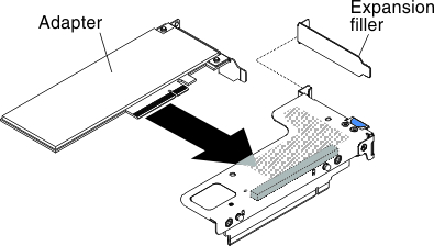 Figure 2. Adapter installation into a PCI riser-card assembly that has one low-profile slot for ML2 card (for PCI riser-card assembly connector 1 on system board)
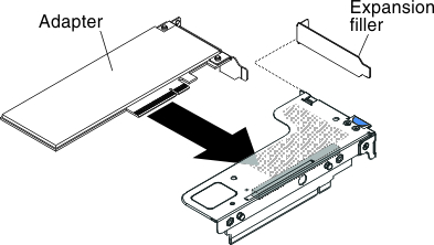 Figure 3. Adapter installation into a PCI riser-card assembly that has one low-profile slot (for PCI riser-card assembly connector 2 on system board)
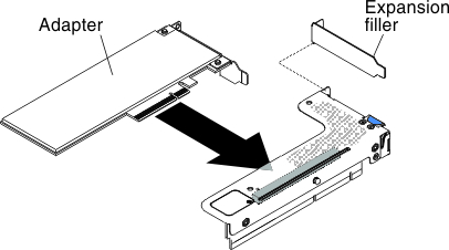 Figure 4. Adapter installation into a PCI riser-card assembly that has two low-profile slots (for PCI riser-card assembly connector 2 on system board)
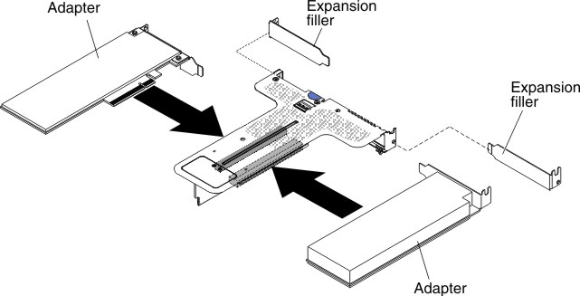 Figure 5. Adapter installation into a PCI riser-card assembly that has one low-profile slot and one full-height half-length slot (for PCI riser-card assembly connector 2 on system board)
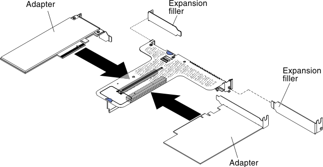 AttentionWhen you install an adapter, make sure that the adapter is correctly seated in the riser-card assembly and that the riser-card assembly is securely seated in the riser-card connector on the system board before you turn on the server. An incorrectly seated adapter might cause damage to the system board, the riser-card assembly, or the adapter.