Replacing the front video connector assembly
Use this information to replace the front video connector assembly.
To install the front video connector assembly, complete the following steps:
- From inside the media cage, insert the front video connector assembly into the holes on the cage; then, install the screws to secure the assembly to the cage.NoteRefer to the illustration that applies to your particular server configuration.
Eight 2.5-inch hot-swap or simple-swap hard disk drive server configuration:
Figure 1. Front video connector assembly installation for eight 2.5-inch hot-swap or simple-swap hard disk drive server configuration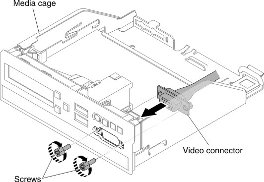
Ten 2.5-inch hot-swap hard disk drive server configuration:
Figure 2. Front video connector assembly installation for ten 2.5-inch hot-swap hard disk drive server configuration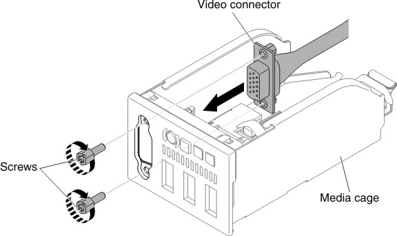
Four 3.5-inch hot-swap or simple-swap hard disk drive server configuration:
Figure 3. Front video connector assembly installation for four 3.5-inch hot-swap or simple-swap hard disk drive server configuration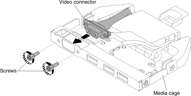
Give documentation feedback