Replacing a hot-swap hard disk drive backplane
Use this information to replace a hot-swap hard disk drive backplane.
To install the replacement hot-swap hard disk drive backplane, complete the following steps:
- Install the hot-swap hard disk drive backplane. Based on the server configuration, the hot-swap hard disk drive backplane may appear as either of the following four.
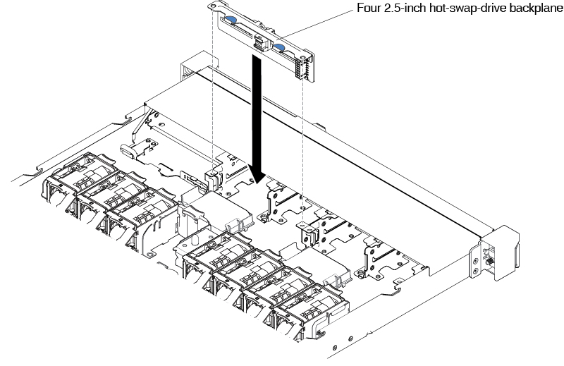
Steps for installing a four 2.5-inch hot-swap hard disk drive backplane
NoteTwo four 2.5-inch hot-swap-drive backplanes are used for the eight 2.5-inch hot-swap-drive server model.- Carefully lower the hard disk drive backplane until it is fully seated in the chassis.Figure 1. Four 2.5-inch hot-swap-drive backplane installation
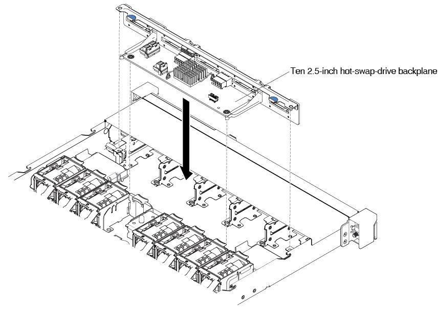
Steps for installing a ten 2.5-inch hot-swap-drive backplane
- Carefully lower the hard disk drive backplane until it is fully seated in the chassis.Figure 2. Ten 2.5-inch hot-swap-drive backplane installation
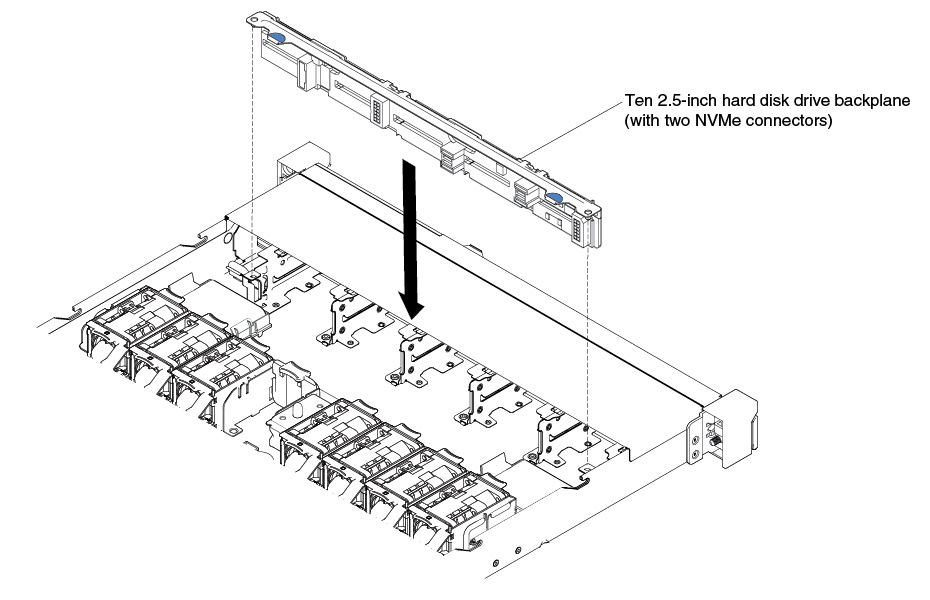
Steps for installing a ten 2.5-inch hot-swap hard disk drive backplane with two NVMe drive connectors
- Carefully lower the hard disk drive backplane until it is fully seated in the chassis.Figure 3. Installation of a 10 x 2.5-inch hot-swap hard disk drive backplane with two NVMe connectors
Steps for installing a four 3.5-inch hot-swap-drive backplane
- Secure the backplane to the chassis by pressing the release latches.Figure 4. Four 3.5-inch hot-swap-drive backplane installation
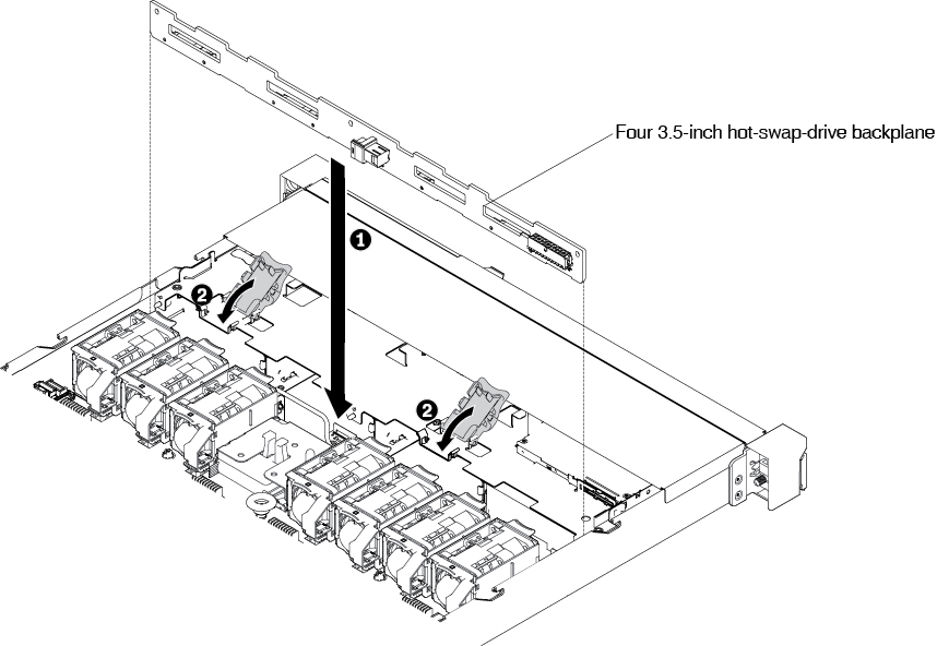
- Carefully lower the hard disk drive backplane until it is fully seated in the chassis.
- Route the signal cable from the drive backplane along the chassis and connect it to the SAS/SATA controller connectors. Then, route the power cable and the configuration cable from the drive backplane along the chassis and connect it to the SAS/SATA power connector and SAS/SATA configuration connector. For the 10 x 2.5-inch drive backplane with two NVMe connectors, connect the NVMe cable to the NVMe adapter and the backplane. The following illustrations show the cable routing and connectors for the 2.5-inch and 3.5-inch hot-swap backplanes.Figure 5. Eight 2.5-inch hot-swap backplane cable connection
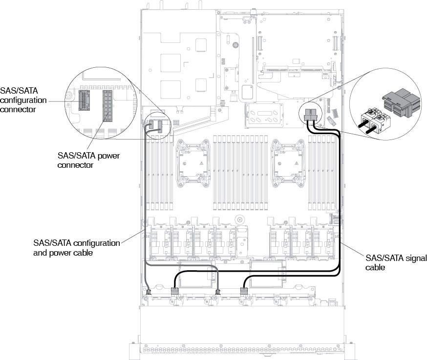 Figure 6. Ten 2.5-inch hot-swap backplane cable connection
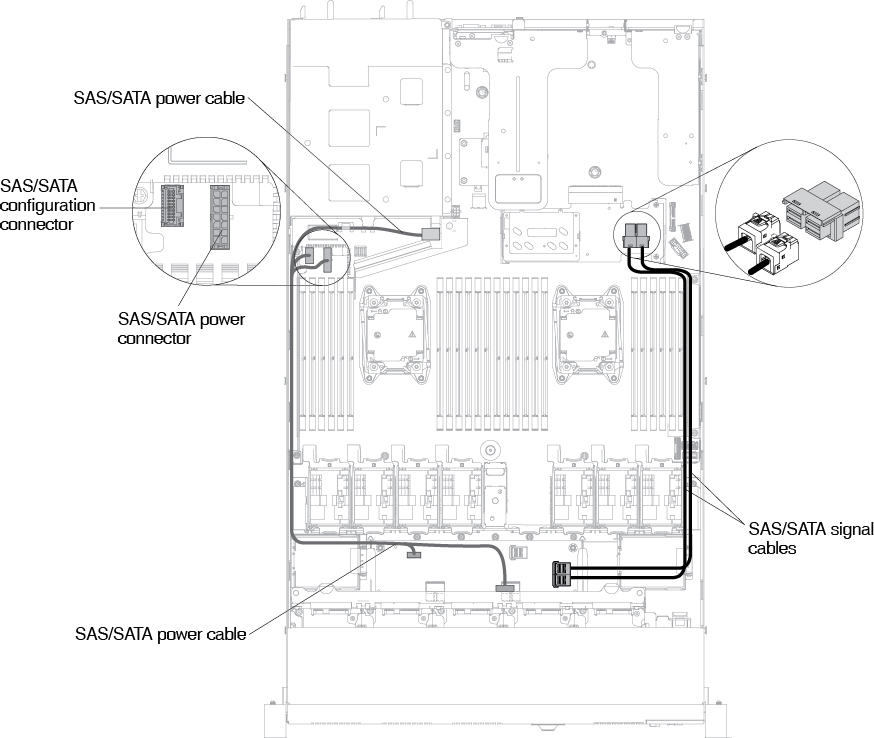 Figure 7. Cable connection for a ten 2.5-inch hot-swap backplane with two NVMe connectors
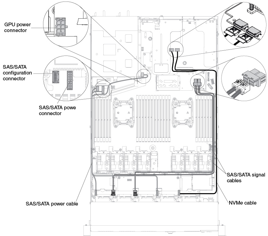 Figure 8. Twelve 2.5-inch hot-swap backplane cable connection
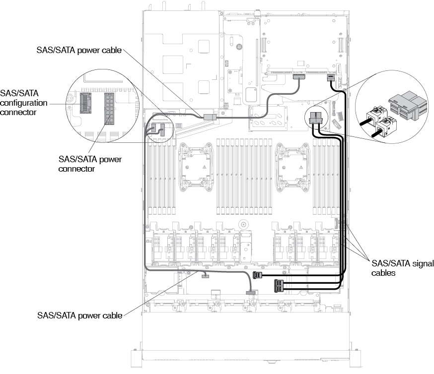 Figure 9. Four 3.5-inch hot-swap-drive backplane installation
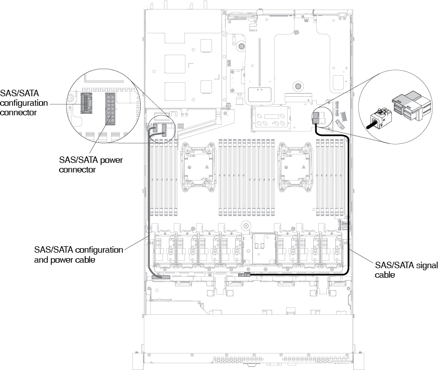
Give documentation feedback