Use this information to replace a PCI riser-card assembly.
PCI riser-card brackets must be installed even if you do not install an adapter.
The following table lists the supported PCI riser-card assembly configurations in the server.
Table 1. Configuration 1. The PCI riser-card assembly configuration 1 table description table.
| Configuration 1 |
|---|
| Configuration | Number of microprocessors installed | PCI riser-card assembly connector 1 on system board | PCI riser-card assembly connector 2 on system board |
|---|
| Slot 1 | Slot 2 | Slot 3 |
|---|
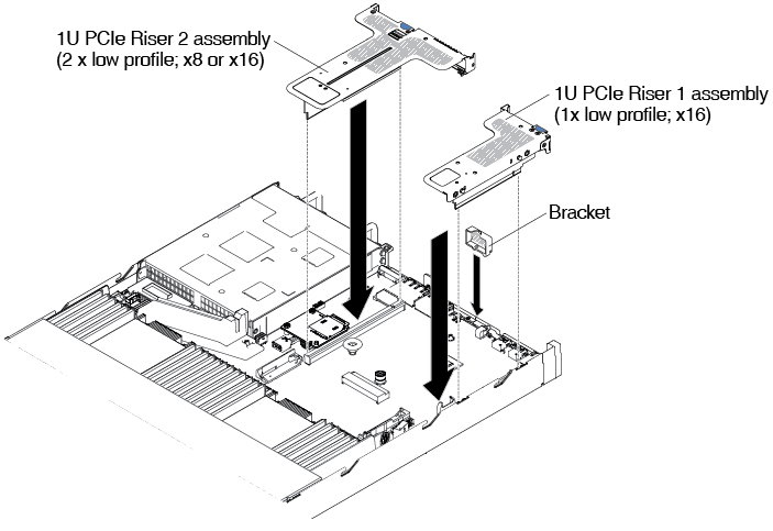
| One | x1/x4/x8/x16 low-profile | x1/x4/x8 low-profile | x1/x4/x8 low-profile |
Table 2. Configuration 2. The PCI riser-card assembly configuration 2 table description table.
| Configuration 2 |
|---|
| Configuration | Number of microprocessors installed | PCI riser-card assembly connector 1 on system board | PCI riser-card assembly connector 2 on system board |
|---|
| Slot 1 | Slot 2 | Slot 3 |
|---|
| Two | x1/x4/x8/x16 low-profile | x1/x4/x8/x16 low-profile | x1/x4/x8/x16 low-profile |
Table 3. Configuration 3. The PCI riser-card assembly configuration 3 table description table.
Slot 1 is for the 60-mm ML2 adapter.
| Configuration 3 |
|---|
| Configuration | Number of microprocessors installed | PCI riser-card assembly connector 1 on system board | PCI riser-card assembly connector 2 on system board |
|---|
| Slot 1 | Slot 2 | Slot 3 |
|---|
- One ML2 slot
- One full-height, half-length slot
- One low-profile slot
| One | ML2 | x1/x4/x8 full-height, half-length | x1/x4/x8 low-profile |
Table 4. Configuration 4. The PCI riser-card assembly configuration 4 table description table.
Slot 1 is for the 60-mm ML2 adapter.
| Configuration 4 |
|---|
| Configuration | Number of microprocessors installed | PCI riser-card assembly connector 1 on system board | PCI riser-card assembly connector 2 on system board |
|---|
| Slot 1 | Slot 2 | Slot 3 |
|---|
- One ML2 slot
- One half-length, full-height slot
- One low-profile slot
| Two | ML2 | x1/x4/x8/x16 full-height, half-length | x1/x4/x8/x16 low-profile |
Table 5. Configuration 5. The PCI riser-card assembly configuration 5 table description table.
Slot 1 is for standard low-profile ML2 adapter.
| Configuration 5 |
|---|
| Configuration | Number of microprocessors installed | PCI riser-card assembly connector 1 on system board | PCI riser-card assembly connector 2 on system board |
|---|
| Slot 1 | Slot 2 | Slot 3 |
|---|
- One ML2 slot
- Two low-profile slots
| One | ML2 | x1/x4/x8 low-profile | x1/x4/x8 low-profile |
Table 6. Configuration 6. The PCI riser-card assembly configuration 6 table description table.
Slot 1 is for standard low-profile ML2 adapter.
| Configuration 6 |
|---|
| Configuration | Number of microprocessors installed | PCI riser-card assembly connector 1 on system board | PCI riser-card assembly connector 2 on system board |
|---|
| Slot 1 | Slot 2 | Slot 3 |
|---|
- One ML2 slot
- Two low-profile slots
| Two | ML2 | x1/x4/x8/x16 low-profile | x1/x4/x8/x16 low-profile |
Table 7. Configuration 7. The PCI riser-card assembly configuration 7 table description table.
| Configuration 7 |
|---|
| Configuration | Number of microprocessors installed | PCI riser-card assembly connector 1 on system board | PCI riser-card assembly connector 2 on system board |
|---|
| Slot 1 | Slot 2 | Slot 3 |
|---|
- One rear 2.5-inch hot-swap-drive kit
- One low-profile slot
| One or two | X | X | x1/x4/x8/x16 low-profile |
To install a PCI riser-card assembly, complete the following steps:
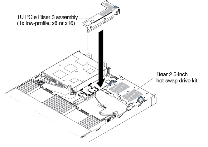 Figure 2. PCI riser-card assembly installation (2)
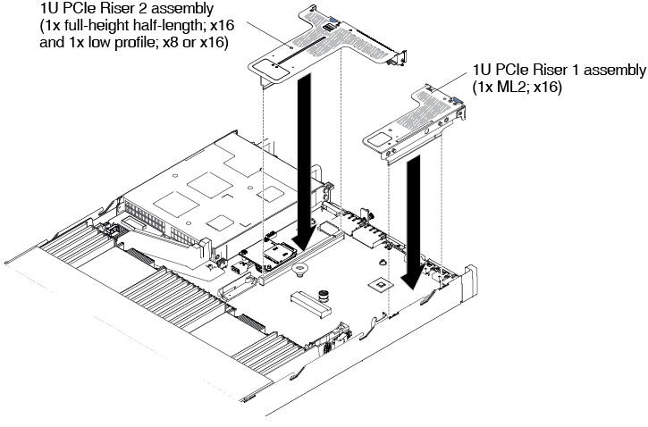 Figure 3. PCI riser-card assembly installation (3)
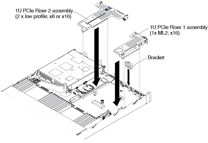 Figure 4. PCI riser-card assembly installation (4)