Installing a memory module
Use these instructions to install memory modules in the blade server.
The blade server has a total of sixteen direct inline memory module (DIMM) slots. The blade server supports very low profile (VLP) DDR3 DIMMs with error code correction (ECC) in 4 GB, 8 GB, and 16 GB capacities. For a list of supported DIMMs for the blade server, see Parts listing.
After you install or remove a DIMM, you must change and save the new configuration information by using the Setup utility. When you turn on the blade server, a message indicates that the memory configuration has changed. Start the Setup utility and select Save Settings (see Setup utility menu for more information) to save changes.
The memory is accessed internally through the system using four channels per microprocessor. Each channel contains two DIMM connectors. The following table lists each channel and which DIMM connectors belong to the channel.
| Memory channel | DIMM connector (microprocessor 1) | DIMM connector (microprocessor 2) |
|---|---|---|
| Channel 0 | 7 and 8 | 15 and 16 |
| Channel 1 | 1 and 2 | 13 and 14 |
| Channel 2 | 3 and 4 | 9 and 10 |
| Channel 3 | 5 and 6 | 11 and 12 |
Depending on the memory mode that is set in the Setup utility, the blade server can support a minimum of 4 GB and a maximum of 128 GB of system memory on the system board in a blade server with one microprocessor. If two microprocessors are installed, the blade server can support a minimum of 8 GB and a maximum of 256 GB of system memory. There are four different memory modes:
- Independent channel mode: Independent channel mode gives a maximum of 128 GB of usable memory with one microprocessor installed, and 256 GB of usable memory with two microprocessors installed (using 16 GB DIMMs). The DIMMs can be installed without matching sizes. See the table below for the memory installation order.
- Rank sparing mode: In rank sparing mode, one rank of a DIMM in each populated channel is reserved as spare memory. The spare rank is not available as active memory. When the active rank memory fails, its content is copied to the spare rank memory which becomes active. The memory set aside for spare is one rank per channel. The size of a rank varies depending on the DIMMs installed. The DIMM population ordering for rank sparing mode is the same as that for independent channel mode.
Table 2. DIMM population sequence for independent-channel mode and rank-sparing mode One microprocessor installed Two microprocessors installed DIMM connectors 1, 7, 3, 5, 2, 8, 4, and 6 DIMM connectors 1, 16, 7, 14, 3, 9, 5, 11, 2, 15, 8, 13, 4, 10, 6, and 12 - Mirrored channel mode: In mirrored channel mode, the memory contents on channel 0 are duplicated in channel 2, and the memory contents of channel 1 are duplicated in channel 3. The effective memory available to the system is only half of that installed. The maximum available memory (with 16 GB DIMMs) is 64 GB for a single microprocessor system and 128 GB for a dual microprocessor system.ImportantThe memory configuration of channel 0 must match that of channel 2, and the memory configuration of channel 1 must match that of channel 3. For example, if a 4 GB Dual Rank DIMM is installed into the DIMM connector 3 (channel 0), then a 4 GB Dual Rank DIMM must also be installed into the DIMM connector 7 (channel 2).
Memory channel configuration lists each channel and which DIMM connectors belong to the channel. The following table shows the order that memory DIMMs are installed to use a mirrored channel mode.
Table 3. DIMM population sequence for mirrored channel mode DIMM pair DIMM connectors One microprocessor installed Two microprocessors installed First 1 and 7 1 and 7 Second 3 and 5 14 and 16 Third 2 and 8 3 and 5 Fourth 4 and 6 9 and 11 Fifth None 2 and 8 Sixth None 13 and 15 Seventh None 4 and 6 Eighth None 10 and 12 NoteThe DIMM pairs must be identical in size, type, and rank count.
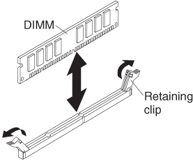
To install a DIMM, complete the following steps:
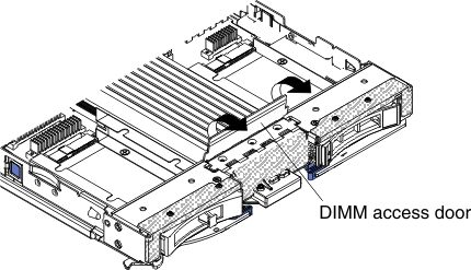
- If you are installing a DIMM in DIMM connector seven through twelve, use your fingers to lift the DIMM access door.
- To install the DIMMs, repeat the following steps for each DIMM that you install: