Connecting the chassis to power
Power is supplied to the Flex System Carrier-Grade chassis when one end of each power cord is connected to a power connector on the rear of the chassis and the other end of each power cord is connected to a power source. The Flex System Carrier-Grade chassis dc-power inputs are configured for dc isolated return (DC-I). The dc RETURN (RTN) terminal or conductor is not connected to the equipment frame or the grounding means of the equipment.
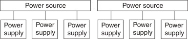
Connecting for N+N power redundancy
The Flex System Carrier-Grade chassis can have up to six power supplies. The chassis allows you to populate power supplies to meet the load demand that is installed in the chassis. As more nodes are installed in the chassis, you can install additional power supplies to meet the increased load demand.
To provide power source redundancy for the chassis, you can connect the power supplies in an N+N configuration, where N can be 1, 2 , or 3, depending on the total load installed in the chassis. In this configuration, the power-supply power cords are connected to separate sources. If a supply circuit fails, the remaining power supplies have enough power available to power the entire chassis load. A fully configured chassis with N+N power redundancy has six power supplies.
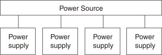
Connecting for N+1 power redundancy
If power source redundancy is not a concern but you want power supply redundancy, you can connect the power supplies in an N+1 configuration, where N can be 1, 2, 3, 4, or 5 depending on the total load that is installed in the chassis. In this configuration, the power-supply power cords are connected to the same source but there is one extra power supply available (+1). If one of the power supplies fails, the remaining power supplies have enough power available to power the entire chassis load. If two or more power supplies fail, it is possible for the entire chassis to lose power. If the power source circuit fails, the entire chassis will lose power.
Statement 29
- This equipment shall be connected directly to the dc supply system earthing electrode conductor or to a bonding jumper from an earthing terminal bar or bus to which the dc supply system earthing electrode conductor is connected.
- This equipment shall be located in the same immediate area (such as, adjacent cabinets) as any other equipment that has a connection between the earthed conductor of the same dc supply circuit and the earthing conductor, and also the point of earthing of the dc system. The dc system shall not be earthed elsewhere.
- The dc supply source shall be located within the same premises as this equipment.
- Switching or disconnecting devices shall not be in the earthed circuit conductor between the dc source and the point of connection of the earthing electrode conductor.
Statement 31
To avoid a shock hazard:
- Do not connect or disconnect any cables or perform installation, maintenance, or reconfiguration of this product during an electrical storm.
- Connect all power cords to a properly wired and grounded power source.
- Connect to properly wired power sources any equipment that will be attached to this product.
- When possible, use one hand only to connect or disconnect signal cables.
- Never turn on any equipment when there is evidence of fire, water, or structural damage.
- Disconnect the attached ac power cords, dc power sources, network connections, telecommunications systems, and serial cables before you open the device covers, unless you are instructed otherwise in the installation and configuration procedures.
- Connect and disconnect cables as described in the following table when you install, move, or open covers on this product or attached devices.
| To Connect: | To Disconnect: |
|---|---|
|
|
Statement 34
- This equipment must be installed by trained service personnel in a restricted-access location, as defined by the NEC and IEC 60950-1, First Edition, The Standard for Safety of Information Technology Equipment.
- Connect the equipment to a properly grounded safety extra low voltage (SELV) source. A SELV source is a secondary circuit that is designed so that normal and single fault conditions do not cause the voltages to exceed a safe level (60 V direct current).
- Incorporate a readily available approved and rated disconnect device in the field wiring.
- See the specifications in the product documentation for the required circuit-breaker rating for branch circuit overcurrent protection.
- Use copper wire conductors only. See the specifications in the product documentation for the required wire size.
- See the specifications in the product documentation for the required torque values for the wiring-terminal screws.
| Breaker | Listed 70 A | See Note 1 |
| Ground cable | 4 AWG with Listed lug which can accept M6 ground screws | See Note 2 |
| Torque rating for ground screws | 4.0 - 4.8 Newton-meters (35.4 - 42.5 inch-pounds) | - |
| ||
To connect the chassis to power, complete the following steps:
- For dc-powered chassis:
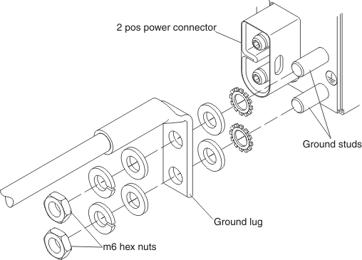
- For a chassis powered by -48 to -60 V dc power supplies (restricted-access location is required), connect an earth ground cable to each power supply.
- Use a 10 mm nut driver to remove the hex nuts from the ground studs.
- Remove the lock washer and one of the flat washers from each ground stud.
- Push the ground lug onto the ground studs; then, place the flat washer, the lock washer, and the hex nut back on each ground stud.
- Use a 10 mm nut driver to tighten the hex nuts to 4.0 - 4.8 Newton-meters (35.4 - 42.5 inch-pounds).
- Connect each power cord from the dc power supplies to a dc power distribution panel (PDP) (restricted-access location is not required).Attention
- Do not route the power cords over removable modules or allow the cords to interfere with the module handles.
- In North America, connect the power cords to a UL-listed PDP only.
- For a chassis powered by -48 to -60 V dc power supplies (restricted-access location is required), connect an earth ground cable to each power supply.
- For an ac-powered chassis (restricted-access location is not required), connect each power cord from the power supplies to a power distribution unit (PDU), uninterruptible power source (UPS) or wall receptacle. AC power is supplied to the Flex System Carrier-Grade chassis by one of the following options:
- A power cord that connects to a PDU or UPS supplying a maximum 20 A branch circuit protection.
- A power cord that connects to a wall receptacle supplying a maximum 20 A branch circuit protection.
- A special use Flex System 3X Power Cord that connects to a wall receptacle supplying a maximum 32 A branch circuit protection.
AttentionDo not route the power cords over removable modules or allow the cords to interfere with the module handles. - Make sure that the following LEDs are lit:
- The logo on the chassis front information panel.
- The dc power in or ac power in and dc power out LEDs on each power supply.
- The power LED on each I/O module.
NoteThe power LED on eachcompute node and on the Flex System Manager management node, if one is installed, flashes slowly to indicate that the node is connected to power and is ready to be turned on. - If the LEDs are not lit:
- Disconnect the chassis from the power source.
- Reseat all of the components in the chassis.
- Reconnect the chassis to the power source.
- If the problem persists, contact Support.