Fan modules
The Flex System Carrier-Grade chassis supports up to ten fan modules (two 40 mm fan modules and eight 80 mm fan modules). It comes with a minimum of six hot-swap fan modules installed (four 80 mm fan modules and two 40 mm fan modules).
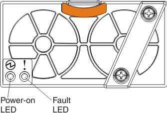
40 mm fan modules
The two smaller 40 mm fan modules at the top of the chassis provide cooling to the I/O modules and the CMMs. The following is an illustration of the 40 mm fan modules:
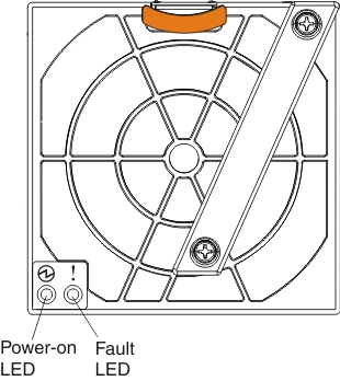
80 mm fan modules
The larger 80 mm fan modules provide cooling to the compute nodes. The following is an illustration of the 80 mm fan modules:
Note
Not all of the 80 mm fan modules are required. Empty 80 mm fan bays must have a filler installed to maintain adequate cooling. See Installing components to determine the number of 80 mm fan modules required and where they should be installed in your configuration.
Fan zones
Compute node cooling is logically split between the left and right half of the chassis. The ten fan modules provide cooling in four zones as shown in the following illustration:
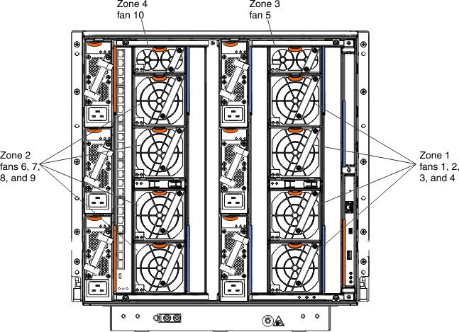
- Zone 1 includes four 80 mm fan modules numbered 1, 2, 3, and 4 on the right rear of the chassis. Zone 1 fans provide cooling for the odd-numbered node bays (1, 3, 5, 7, 9, 11, and 13) on the left front of the chassis. These fans provide airflow to the nodes directly in front of them.
- Zone 2 contains four 80 mm fan modules numbered 6, 7, 8, and 9 on the left rear of the chassis. Zone 2 fans provide cooling for the even-numbered node bays (2, 4, 6, 8, 10, 12, and 14) on the right front of the chassis. These fans provide airflow to the nodes directly in front of them.
- Zone 3 contains one 40 mm fan module (fan 5) on the top right rear of the chassis. Fan 5 provides cooling for I/O modules 2 and 4 as well as both CMMs on the right rear side of the chassis.
- Zone 4 contains one 40 mm fan module (fan 10) on the top left rear of the chassis. Fan 10 provides cooling for I/O modules 1 and 3 on the left rear side of the chassis.
Fan module controls and indicators
The fan modules have two LEDs:
- Power-on LED

When this LED is lit (green), it indicates that the fan module has power.- Fault LED

When this LED is lit (yellow), it indicates that the fan module has failed.
Give documentation feedback