Rear view
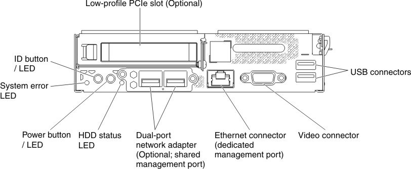
The following illustration shows the connectors and LEDs on the rear of the server.
Figure 1. Connectors on the rear of the server
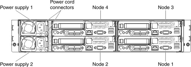
The following illustration shows the rear view of the entire system.
Figure 2. The rear view of the entire system
- Power button/LED: When this LED is lit (green), it indicates that the node has power.
- System error/LED: When this LED is lit (yellow), it indicates that a system error has occurred. Check the event log for additional information.
- ID button/LED: The system administrator can remotely light this LED to aid in visually locating the compute node. When this LED is lit, the identify LED on the chassis is also lit.
- Hard disk drive LED: When this LED is lit, it indicates that one or more hard disk drive has failed.
- Low-profile PCIe slot (optional): Support one PCI Express Gen3 low-profile, half-length adapter.
- Ethernet connectors: Use this dedicated management port to connect the server to a network. When you use the Ethernet 1 connector, the network can be shared with the TMM through NC-SI interface.
- Video connector: Connect a monitor to this connector.
- USB connectors: Connect a USB device, such as a USB mouse, keyboard, or other device to any of these connectors.
- Power cord connector: Connect the power cord to this connector.
Give documentation feedback