System-board switches and jumpers
The following illustration shows the location and description of the switches, jumpers, and buttons.
Important
- Before you change any switch settings or move any jumpers, turn off the server; then, disconnect external cables. Review the information in Safety, Installation guidelines, and Turning off the server.
- Any system-board switch or jumper block that is not shown in the illustrations in this document are reserved.
- If there is a clear protective sticker on the switch blocks, you must remove and discard it to access the switches.
Figure 1. Location of the switches, jumpers, and buttons on the system board
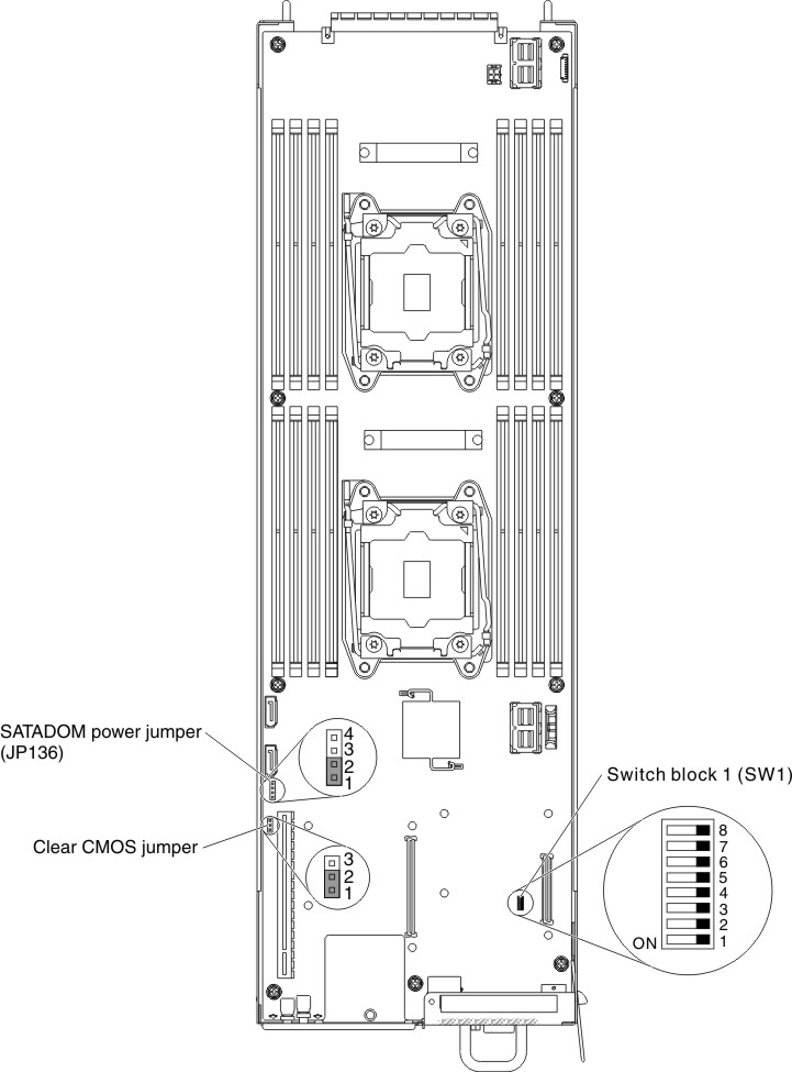
The following table describes the jumpers on the system board.
| Jumper name | Description |
|---|---|
| Clear CMOS jumper |
|
| SATADOM power jumper (JP136) |
Warning Warning: Do not surround Pin 3 and 4 with SATADOM power jumper. |
The following table describes the functions of the SW1 switch block on the system board.
| Switch number | Default position | Description |
|---|---|---|
| 1 | Off | BIOS recovery. |
| 2 | Off | ME recovery. |
| 3 | Off | Default off. |
| 4 | Off | Password clear. |
Give documentation feedback