Installing a scalability and performance connector
Use this information to install a scalability and performance connector.
Before you install a scalability and performance connector, complete the following steps:
- Read Safety and Installation guidelines.
- If the compute node is operating, shut down the operating system.
- Press the power button to turn off the compute node (see Turning off the compute node for more information).
Notes
- If you purchased a multi-node complex and you received each compute node packaged individually, each compute node has a label on the top of the bezel identifying the primary node and the secondary nodes as defined at the factory during testing. Install the nodes in the chassis in the order indicated on the label with the lowest number on the bottom and the highest number on top.
- When you press the power-control button on any compute node in a single partition (controlled by one operating system), all compute nodes in the single partition will be turned on or turned off.
- To consider any maximum I/O limitations, see http://www.ibm.com/systems/info/x86servers/serverproven/compat/us/nos/flexmatrix.shtml.
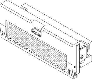
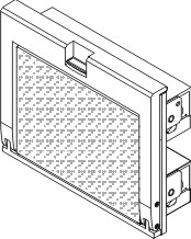
The information in this topic applies to the optional scalability and performance connectors available for the compute node:
- Flex System X6 2-Socket Performance Accelerator
 ImportantThe compute node must have Intel Xeon E7-4800v3 microprocessors, or E7-8800v3 microprocessors to support the two-socket performance connector.
 - Flex System X6 4-Socket Scalability Connector
 ImportantThe compute nodes must have Intel Xeon E7-4800v3 microprocessors or E7-8800v3 microprocessors to form a two-node (four-socket) complex.
 - Flex System X6 8-Socket Scalability Connector
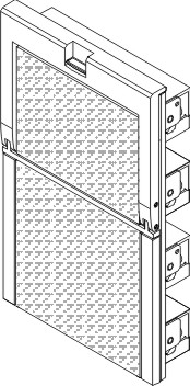 ImportantThe compute nodes must have Intel Xeon E7-8800v3 microprocessors to form a four-node (eight-socket) complex.
To install a scalability and performance connector, complete the following steps.
- Remove the protective covers from the connectors on the scalability and performance connector.

- Align the guide pins on the scalability and performance connector with the guide pin sockets on the compute node and press the connector against the compute node.
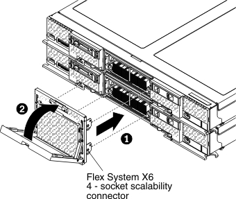 NoteMake sure that the handle is in the open position to engage the connector with the compute node.
See Working with scalable partitions for information about configuring, modifying, and deleting scalable partitions.
Give documentation feedback