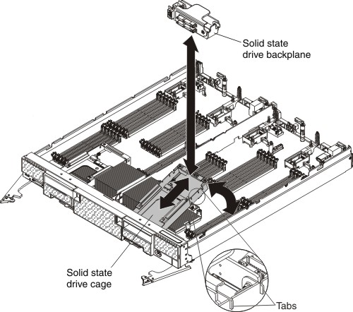
Installing the solid state drive cage and backplane
Use this information to install the solid state drive cage and backplane.
Before you install the solid state drive cage and backplane, complete the following steps:
- Read Safety and Installation guidelines.
- If the compute node is installed in a Lenovo Flex System chassis, remove it (see Removing a compute node from a chassis for instructions).
- Carefully lay the compute node on a flat, static-protective surface, orienting the compute node with the bezel pointing toward you.
The solid state drive cage and backplane are available in the optional Flex System flash kit.
To install the solid state drive cage and backplane, complete the following steps.
- Remove the cover (see Removing the compute node cover).
- Remove the solid state drive mounting sleeve (see Removing the solid state drive mounting sleeve).
- Position the cage in the drive bay at an angle and rotate the cage into the connector on the system board and make sure it is firmly seated in the connector.
- Press the solid state drive backplane into the solid state drive cage and make sure it is firmly seated in the connector and that the tabs are firmly seated in the cage.
- Install the solid state drive mounting sleeve (see Installing the solid state drive mounting sleeve).
- Install the solid state drives (see Installing a solid state drive).
- Install the solid state drive bezel.
After you install the solid state drive cage and backplane, complete the following steps:
- Install the cover onto the compute node (see Installing the compute node cover for instructions).
- Install the compute node into the chassis (see Installing a compute node in a chassis for instructions).
Give documentation feedback