Water specifications for the secondary cooling loop
It is of crucial importance that water supplied to the heat exchanger meet the requirements listed in this topic. Make sure to meet the requirements before setting up liquid cooling system.
Without the water that is being supplied to the heat exchanger meeting the requirements that are described in this topic, system failures might occur as a result of any of the following problems:
- Leaks due to corrosion and pitting of the metal components of the heat exchanger or the water-supply system.
- Buildup of scale deposits inside the heat exchanger, which can cause the following problems:
- A reduction of the ability of the heat exchanger to cool the air that is exhausted from the rack
- Failure of mechanical hardware, such as a hose quick-connect coupling
- Organic contamination, such as bacteria, fungi, or algae. This contamination can cause the same problems as described for scale deposits.
Control and conditioning of the secondary cooling loop
The water that is used to fill, refill, and supply the heat exchanger must be particle-free deionized water or particle-free distilled water with appropriate controls for avoiding the following issues:
- Metal corrosion
- Bacterial fouling
- Scaling
Materials to use in secondary loops
Use any of the following materials in supply lines, connectors, manifolds, pumps and any other hardware that makes up the closed-loop water-supply system:
- Copper
- Brass with less than 30% zinc content
- Stainless steel 303 or 316
- Peroxide-cured ethylene propylene diene monomer (EPDM) rubber, non-metal-oxide material
Materials to avoid in secondary loops
Do not use any of the following materials in any part of the water-supply system:
- Oxidizing biocides, such as chlorine, bromine, and chlorine dioxide
- Aluminum
- Brass with greater than 30% zinc
- Irons (non-stainless steel)
Water-supply requirements for secondary loops
This section includes specific characteristics of the system that supplies the chilled conditioned water to the heat exchanger.
Temperature:
The heat exchanger and its supply hose and return hoses are not insulated. Avoid any condition that might cause condensation. The temperature of the water inside the supply hose, return hose, and heat exchanger must be kept above the dew point of the location where the heat exchanger is being used.
AttentionTypical primary chilled water is too cold for use in this application because building chilled water can be as cold as 4°C - 6°C (39°F - 43°F).ImportantThe system that supplies the cooling water must be able to measure the room dew point and automatically adjust the water temperature accordingly. Otherwise, the water temperature must be above the maximum dew point for that data center installation. For example, the following minimum water temperature must be maintained:- 18°C ±1°C (64.4°F ±1.8°F). This is applicable within an ASHRAE Class 1 Environmental Specification that requires a maximum dew point of 17°C (62.6°F).
- 22°C ±1°C (71.6°F ±1.8°F). This is applicable within an ASHRAE Class 2 Environmental Specification that requires a maximum dew point of 21°C (69.8°F).
See the ASHRAE document Thermal Guidelines for Data Processing Environments. Information about obtaining this document is at https://www.techstreet.com/ashrae/products/1909403.
Pressure
The water pressure in the secondary loop must be less than 690 kPa (100 psi). Normal operating pressure at the heat exchanger must be 414 kPa (60 psi) or less.
Flow rate
The flow rate of the water in the system must be in the range of 23 - 57 liters (6 - 15 gallons) per minute. Pressure drop versus flow rate for heat exchangers (including quick-connect couplings) is defined as approximately 103 kPa (15 psi) at 57 liters (15 gallons) per minute.
Water volume limits
The heat exchanger holds approximately 9 liters (2.4 gallons). Fifteen meters (50 ft) of 19 mm (0.75 in.) supply and return hoses hold approximately 9.4 liters (2.5 gallons). To minimize exposure to flooding in the event of leaks, the entire product cooling system (heat exchanger, supply hose, and return hose), excluding any reservoir tank, must have a maximum 18.4 liters (4.8 gallons) of water. This is a cautionary statement, not a functional requirement. Also consider using leak detection methods on the secondary loop that supplies water to the heat exchanger.
Air exposure
The secondary cooling loop is a closed loop, with no continuous exposure to room air. After you fill the loop, remove all air from the loop. An air bleed valve is provided at the top of a heat exchanger manifold for purging all air from the system.
Water delivery specifications for secondary loops
This section includes the various hardware components that make up the delivery system secondary loop that provides the chilled, conditioned water to the heat exchanger. The delivery system includes pipes, hoses, and the required connection hardware to connect the hoses to the heat exchanger. Hose management in raised-floor and non-raised-floor environments is also described.
The heat exchanger can remove 100% or more of the heat load from an individual rack when it is running under optimum conditions.
The primary cooling loop is considered to be the building chilled-water supply or a modular chiller unit. The primary loop must not be used as a direct source of coolant for the heat exchanger.
The main purpose of this topic is to provide examples of typical methods of secondary loop setup and operating characteristics that are needed to provide an adequate, safe supply of water to the heat exchanger.
- Comply with ISO 4126-1 (Information about obtaining this document is at https://webstore.ansi.org/Standards/ISO/ISO41262013. Search on document number iso 4126-1.)
- Be installed so that it is easily accessed for inspection, maintenance, and repair.
- Be connected as close as possible to the device that it is intended to protect.
- Be adjustable only with the use of a tool.
- Have a discharge opening that is directed so that discharged water or fluid will not create a hazard or be directed toward any person.
- Be of adequate discharge capacity to ensure that the maximum working pressure is not exceeded.
- Be installed without a shutoff valve between the overpressure safety device and the protected device.
- A method for monitoring and setting the total flow rate delivered to all of the heat exchangers is required. This can be a discrete flowmeter that is built into the flow loop or a flowmeter within the secondary loop of the coolant distribution unit (CDU).
- After you set the total flow rate for all of the heat exchangers by using a flowmeter as previously described, it is important to design the plumbing so that it provides the flow rate that you want for each heat exchanger and provides a way to verify the flow rate. Figure 5 on page 16 through Figure 8 on page 19 illustrate the use of circuit setters to adjust the flow rate to each heat exchanger. Other methods, such as inline or external flowmeters, can provide a more accurate method for setting the flow rate through the individual shutoff valves.
- Design the flow loop to minimize the total pressure drop within the flow loop. The Optional Low Impedance Quick Connect feature (shown in Figure 5 on page 16 through Figure 8 on page 19) cannot be the Eaton quick-connect couplings that are used on the heat exchanger because of the excessive pressure drop associated with flowing through four quick-connect pairs in series. These must be very low, near 0, flow impedance quick connects. Alternatively, these quick connects can be eliminated and replaced with a hose barb connection.
Primary and secondary cooling loops
Figure 1. Primary and secondary cooling loops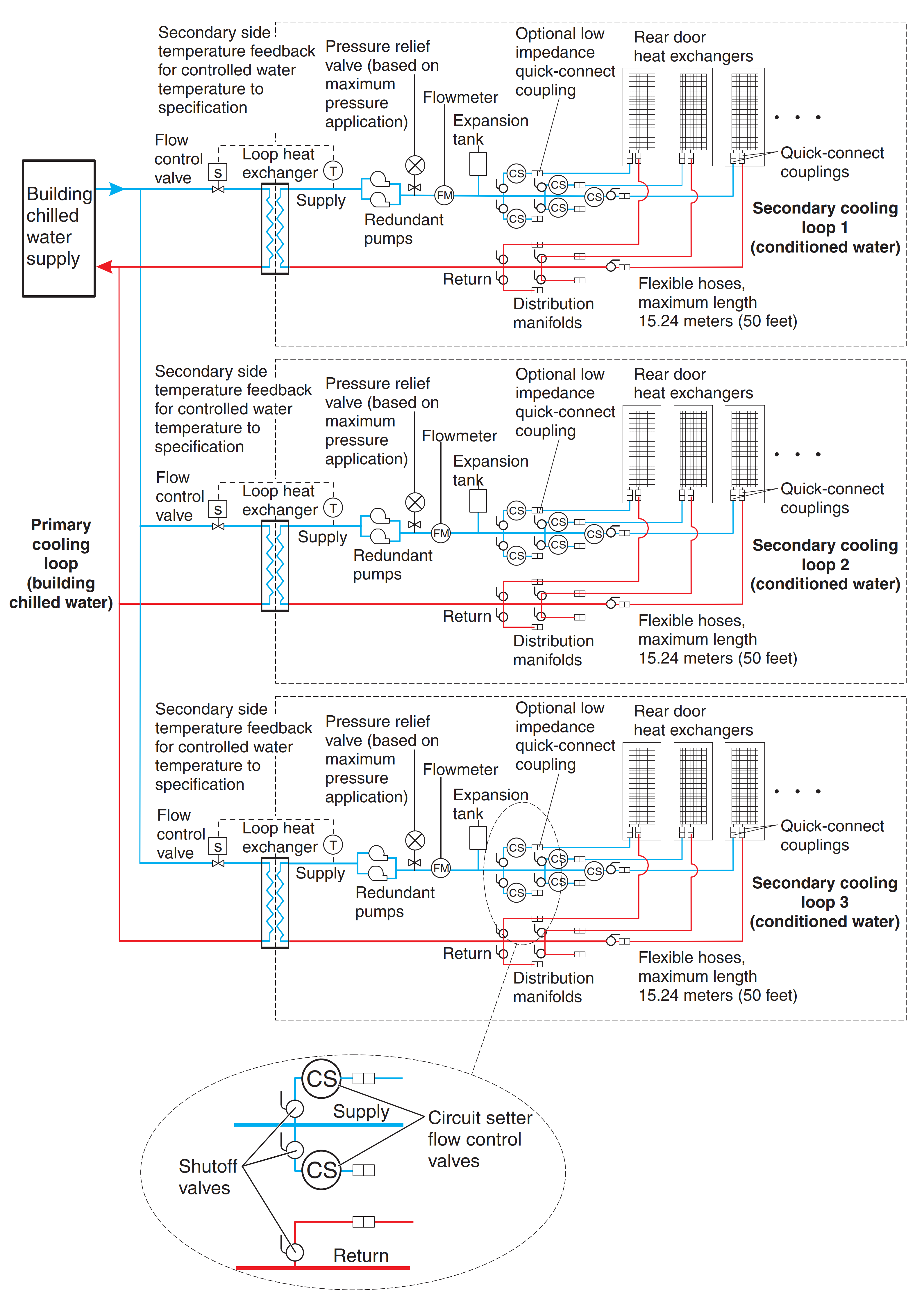
This figure shows a typical cooling solution and identifies the components of the primary cooling loop and the secondary cooling loop.
Coolant distribution unit with a fabricated facilities solution
Figure 2. Coolant distribution unit with a fabricated facilities solution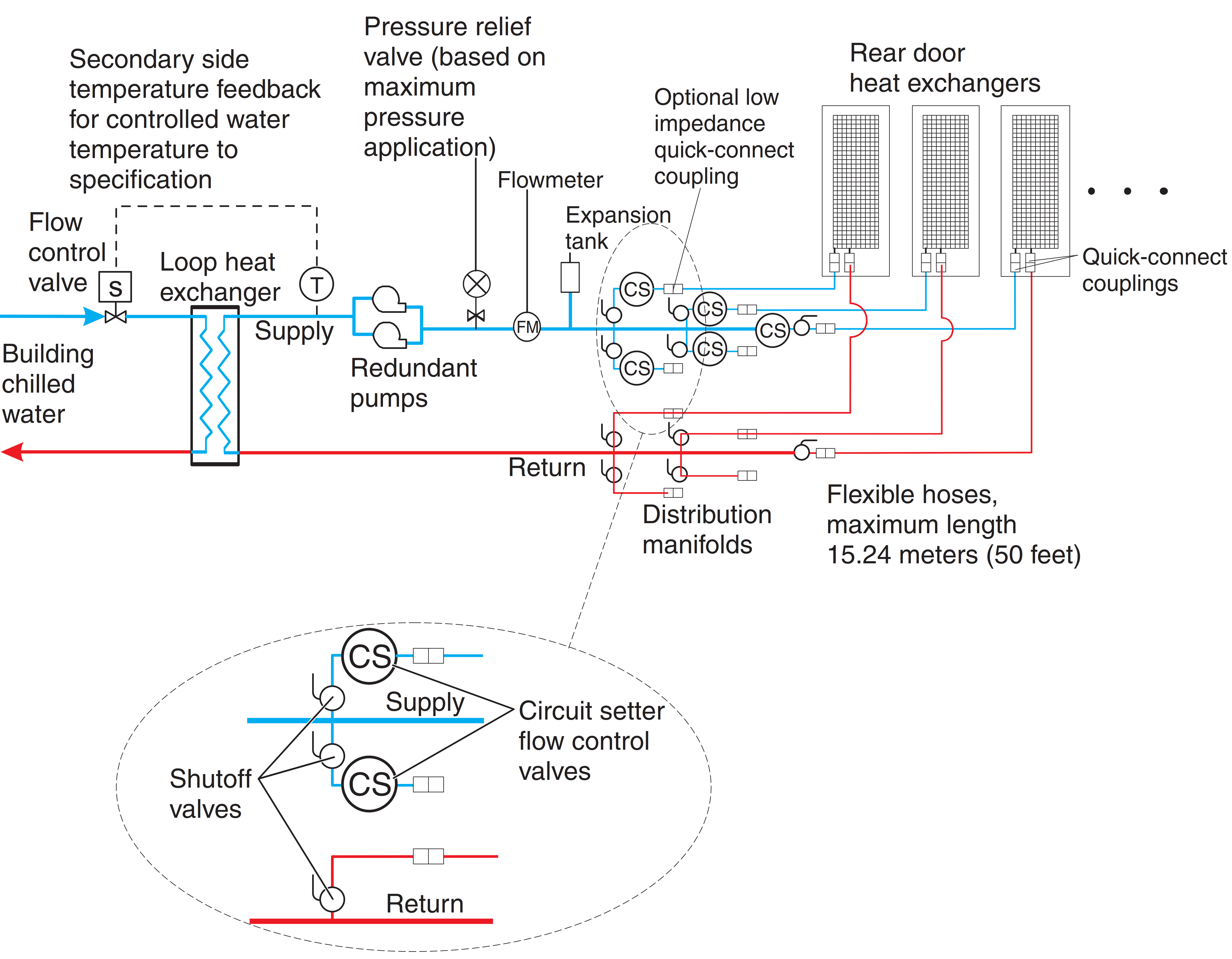
This figure shows an example of a facilities fabricated solution. The actual number of heat exchangers that are connected to a secondary loop depends on the capacity of the coolant distribution unit that is running the secondary loop.
Coolant distribution unit with off-the-shelf supplier solutions
Figure 3. Coolant distribution unit that uses off-the-shelf supplier solutions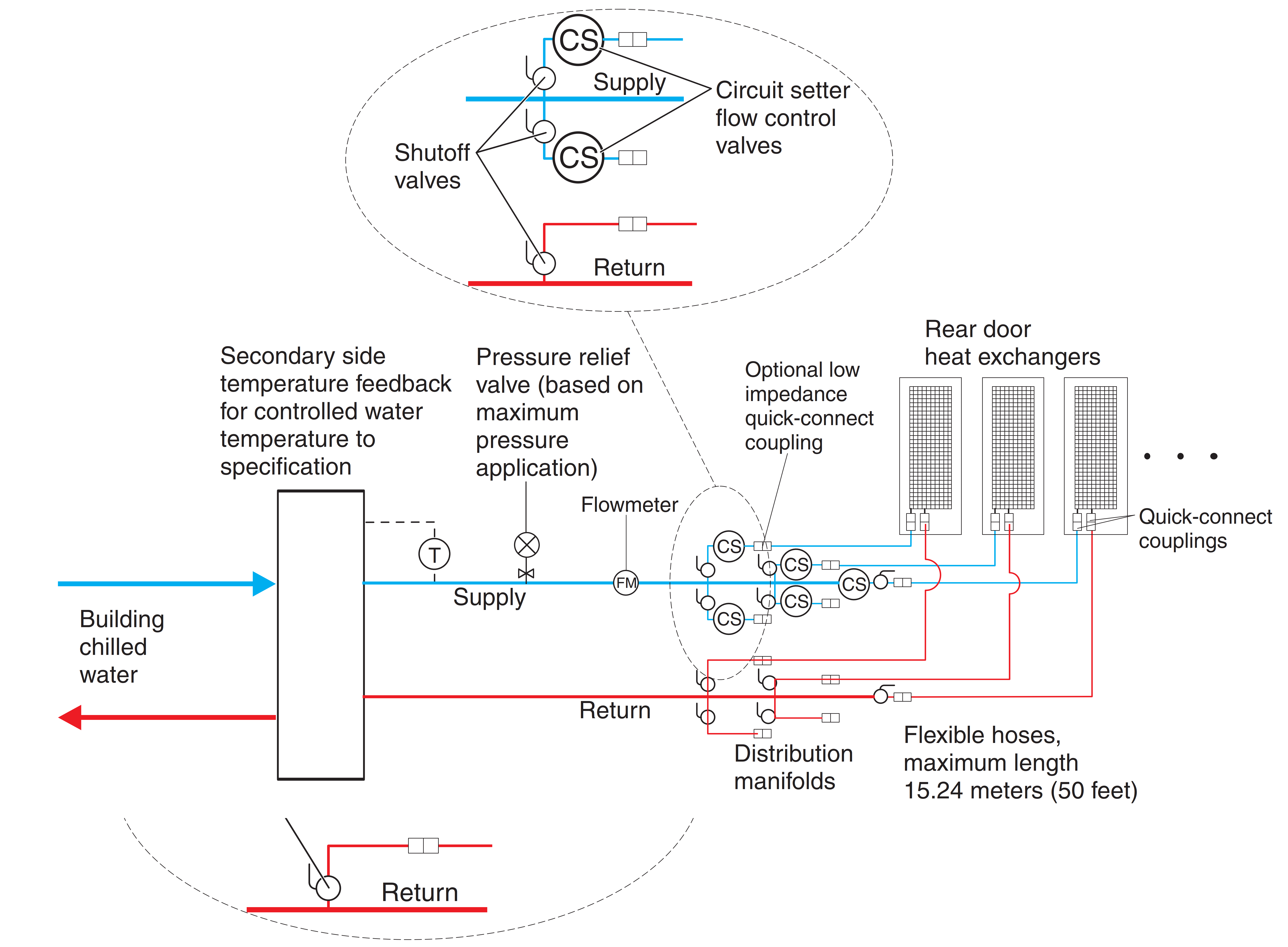 NoteSupplier-built coolant distribution unit (CDU) suggested features:
- Temperature and flow metering (monitoring)
- Leak detection or water level sensing and shutdown
- Local and remote monitoring and control
- Access port for filling and water treatment
This figure shows an example of an off-the-shelf modular coolant distribution unit. The actual number of heat exchangers that are connected to a secondary loop depends on the capacity of the coolant distribution unit that is running the secondary loop
Coolant distribution unit with a water chiller unit to provide conditioned water
Figure 4. Coolant distribution unit that uses off-the-shelf supplier solutions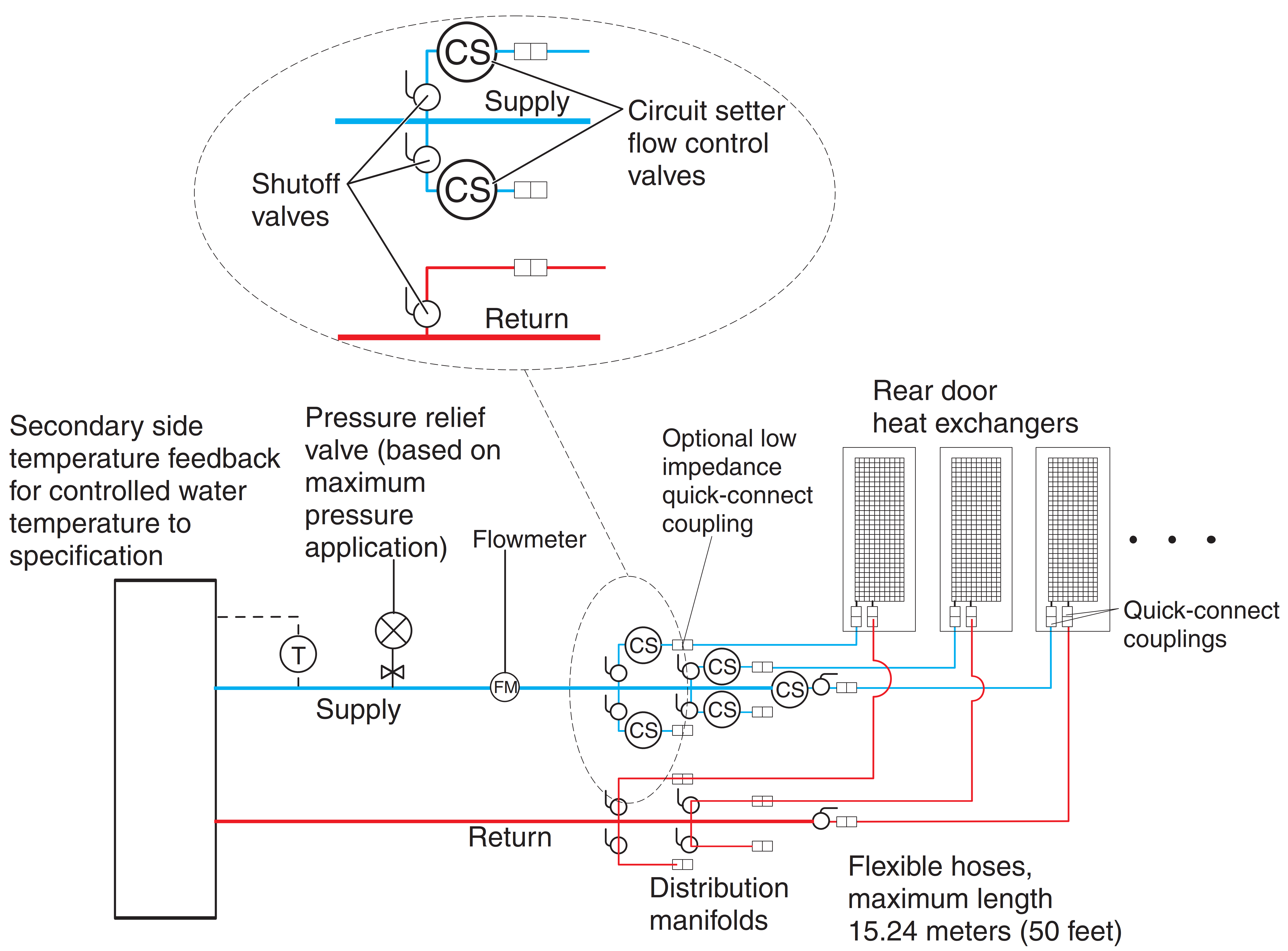 NoteSupplier-built water chiller unit required features:
- Temperature and flow metering (monitoring)
- Leak detection or water level sensing and shutdown
- Local and remote monitoring and control
- Access port for filling and water treatment
This figure shows an example of a water chiller unit that supplies conditioned water to one or more heat exchangers. This must be a closed system (no exposure of the water to air) and meet all materials, water quality, water treatment, and temperature and flow specifications that are defined in this document. A water chiller unit is considered an acceptable alternative to use as a building chilled water source for removing heat from an Rear Door Heat eXchanger.
Manifolds and piping
Manifolds that accept large-diameter feed pipes from a pump unit are the preferred method for splitting the flow of water to smaller-diameter pipes or hoses that are routed to individual heat exchangers. Manifolds must be constructed of materials that are compatible with the pump unit and related piping. The manifolds must provide enough connection points to allow a matching number of supply and return lines to be attached, and the manifolds must match the capacity rating of the pumps and the loop heat exchanger (between the secondary cooling loop and the building chilled-water source). Anchor or restrain all manifolds to provide the required support to avoid movement when quick-connect couplings are connected to the manifolds.
Example manifold supply pipe sizes
- Use a 50.8 mm (2 in.) or larger supply pipe to provide the correct flow to three 19 mm (0.75 in.) supply hoses, with a 100 kW coolant distribution unit (CDU).
- Use a 63.5 mm (2.50 in.) or larger supply pipe to provide the correct flow to four 19 mm (0.75 in.) supply hoses, with a 120 kW CDU.
- Use an 88.9 mm (3.50 in.) or larger supply pipe to provide the correct flow to nine 19 mm (0.75 in.) supply hoses, with a 300 kW CDU.
To stop the flow of water in individual legs of multiple circuit loops, install shutoff valves for each supply and return line. This provides a way to service or replace an individual heat exchanger without affecting the operation of other heat exchangers in the loop.
To ensure that water specifications are being met and that the optimum heat removal is taking place, use temperature and flow metering (monitoring) in secondary loops.
Anchor or restrain all manifolds and pipes to provide the required support and to avoid movement when quick-connect couplings are being attached to the manifolds.
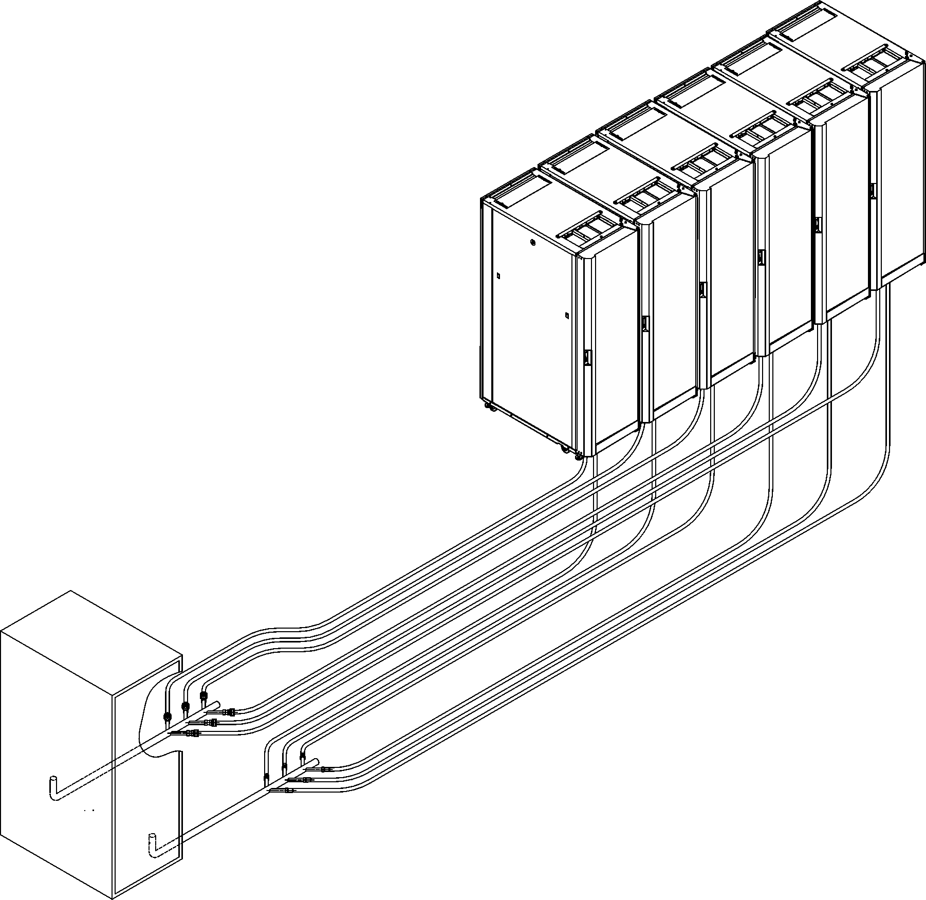
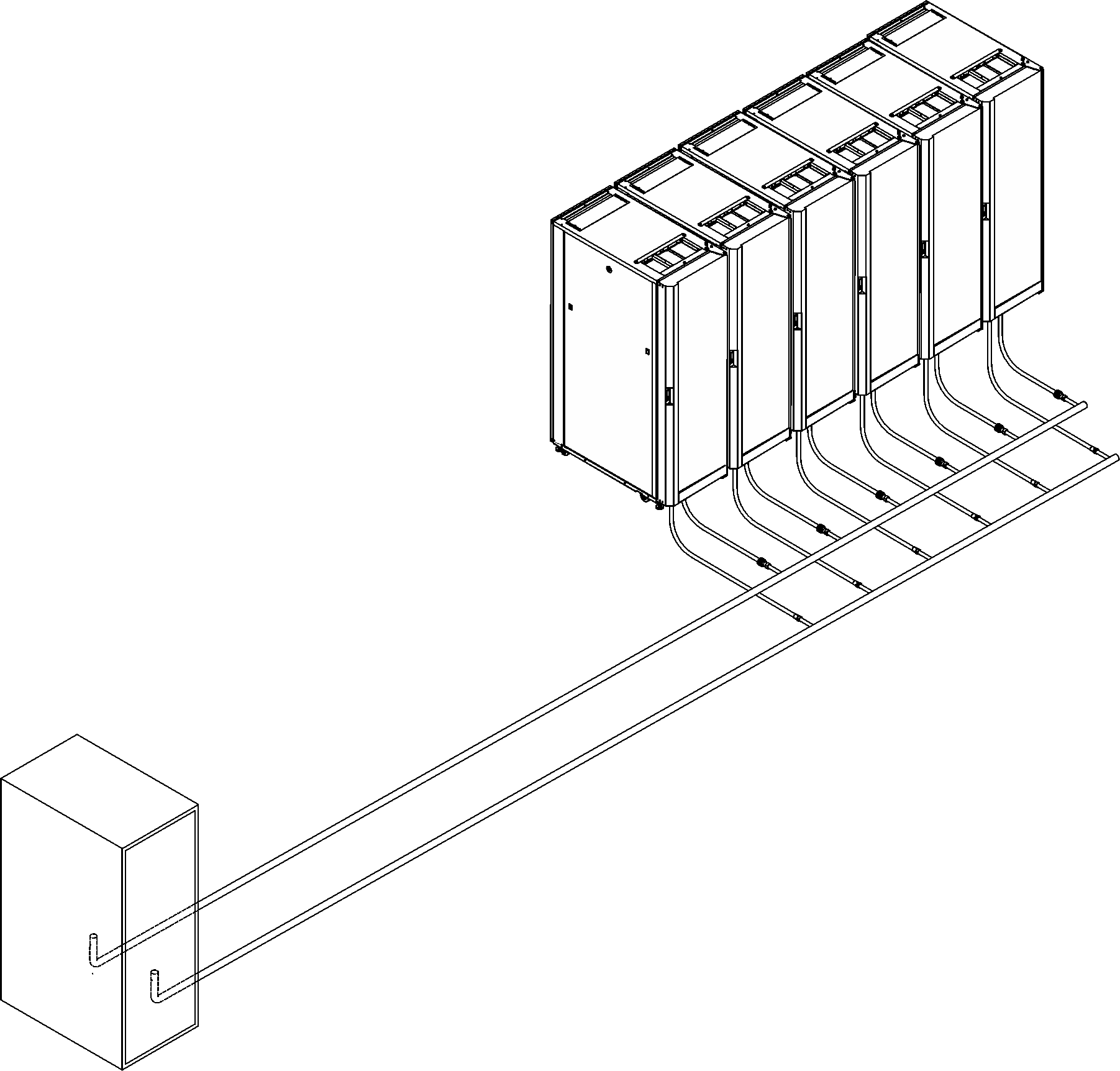
Flexible hoses and connections to manifolds and heat exchangers
Pipe and hose configurations can vary. You can determine the best configuration for your installation by analyzing the needs of your facilities, or a site preparation representative can provide this analysis.
Flexible hoses are needed to supply and return water between your hard plumbing (manifolds and coolant distribution units) and the heat exchanger (allowing needed movement for opening and closing the rack rear door).
Hoses are available that provide water with acceptable pressure-drop characteristics and that help prevent depletion of some corrosion inhibitors. These hoses must be made of peroxide-cured ethylene propylene diene monomer (EPDM) rubber, non-metal oxide material and must have Eaton self-coupling type quick connector ball valve at one end which are attached to the heat exchanger, and must either have a low impedance quick connect coupling or nothing so as to attach to a barb at the other end. The Eaton ball valves that are described in this topic are compatible with the heat exchanger couplings. Hose lengths from 3 to 15 meters (10 to 50 ft), in increments of 3 meters (10 ft), are available. Hoses that are longer than 15 meters (50 ft) might create unacceptable pressure loss in the secondary circuit and reduce the water flow, reducing the heat removal capabilities of the heat exchanger.
Use quick-connect couplings to attach the hoses to the heat exchangers. Hose couplings that connect to the heat exchanger must have the following characteristics:
- The couplings must be constructed of passivated 300-L series stainless steel or brass with less than 30% zinc content. The coupling size is 19 mm (0.75 in.).
- The hoses must have Eaton part number FD83-2046-16-16, or equivalent.
- If a low impedance quick-connect coupling is used at the opposite (manifold) end of the hose, use positive locking mechanisms to prevent loss of water when the hoses are disconnected. The connections must minimize water spill and air inclusion into the system when they are disconnected.